Comedian Ed Wynn opened the first NPE in 1946 with a blast on an injection molded butyrate bugle that replaced scarce brass horns during World War II.
May 1, 2003
|
In this bimonthly column, Glenn Beall of Glenn Beall Plastics Ltd. (Libertyville, IL) shares his special perspective on issues important to design engineers and the molding industry.
The industry has high expectations for the upcoming National Plastics Exposition (NPE) in Chicago next month. In keeping with tradition, this showcase of plastics industry achievements will be opened with great fanfare. The first NPE was held in New York City in 1946, with only 164 exhibitors occupying less than 25,000 sq ft of space. That meeting was called to order by the well-known comedian, Ed Wynn, playing a cellulosic bugle. Cellulosic plastic found wide usage during World War II as a replacement for brass.
John Wesley Hyatt is credited with creating celluloid, the first man-made plastic material. Celluloid was actually a cellulose nitrate. Celluloid started the plastics industry. In its day it was a useful material; however, it was highly flammable and too heat sensitive to be injection molded. Celluloid was crowded out of the market by improved plastic materials. One of these new plastics that traces its linage to celluloid is a family of materials known as the cellulosics.
Eastman Kodak Co. (now Eastman Chemical Products) introduced cellulose acetate (CA) for photographic film in 1927. It received a patent for a molding grade in 1935. Cellulose acetate butyrate (CAB) entered the market in 1938 followed by cellulose acetate propionate (CAP) in 1960. Cellulosics are a unique family of materials; they are not based on oil or natural gas. They are derived from the chemical modification of naturally occurring plant cellulose. Cotton linters are the most common base material for cellulosics.
|
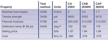
All cellulosics are amorphous, thermoplastic, transparent materials. Light transmission is in the range of 80 to 90 percent. The addition of plasticizers provides different hardness grades within the three members of this family. Typical properties for specific grades of the three types are summarized in Table 1.
Type Selection
Cellulosics are not the strongest, lowest-cost, or the most heat-resistant material available. They are usually chosen for some combination of their toughness, rigidity, abrasion resistance, high gloss, good processing, transparency, and ease of coloring. All types have UL94 HB flammability ratings.
CA is preferred when maximum hardness, stiffness, and tensile strength are required. Some CA provides improved resistance to specific chemical reagents.
CAB and CAP are chosen for their ease of processing and improved dimensional stability. Both types have better weathering ability than CA, with CAB being the better of the two. CAP has the highest heat resistance.
Typical applications include transparent packaging, toothbrushes, automotive steering wheels, tool handles, eyeglass frames, safety lenses, shields, highly decorative writing instruments, figurines, fishing lures, transparent impact-resistant toys, and ETO and irradiation-sterilized medical devices.
Design Considerations
CA, CAB, and CAP are different materials with their own unique properties. In spite of their differences the part design criteria is the same for all three resin types.
Wall thickness. For the easy-flow grades, wall thickness can be as thin as .018 inch for a flow length of 3 inches. One 36-inch-long part was molded with a .100-inch wall. The ideal thickness for these materials is in the range of .030 to .250 inch. These materials do, however, allow the molding of very thick-walled parts with proper gating and molding procedures.
Radiuses. Radiusing on inside corners is not as critical as with other rigid, transparent materials. These materials are not notch sensitive. Inside radiuses can be 25 percent of the part’s wall thickness. The lowest molded-in stress and the highest strength will be achieved with a 75 percent radius.
Draft angles. Draft angles can be as small as 1/2 degree per side. However, angles of 1 degree per side will improve demolding and cycle time.
Cellulosics would not have survived this long without being the ideal material for certain applications.
Projections. Projections off of a part’s nominal wall can have a thickness of 75 percent of the part’s thickness. Small undercuts can be stripped with proper part design and molding procedures.
Depressions. Holes or depressions of all types can be molded without difficulty. Weldline strength and appearance concerns are minimal. The core pins that form holes should incorporate draft angles and avoid sharp corners.
Tolerance. Tolerances are relatively easy to achieve and maintain with these materials. CAB and CAP have slightly better dimensional stability than CA. All three types are amorphous and mold shrinkage is uniform in all directions. A commercial tolerance for a .125-inch-thick, 1-inch-long part is ±.005 inch. A more costly, fine tolerance can be ±.003 inch.
This family of materials has been molded for 68 years, but many engineers are not familiar with them. It must be noted that the cellulosics would not have survived this long without being the ideal material for certain applications.
About the Author(s)
You May Also Like


