Sign up for the PlasticsToday NewsFeed newsletter.
Sponsored By
The basics of injection mold tooling design and its complex interrelationship with part design.
Michael Paloian
August 10, 2022
6 Min Read

Image courtesy of Alamy/Image Source
At a Glance
- There are hundreds of thousands of types of plastic
- Throughout the past 70 years, injection molding has become more sophisticated, versatile, and complicated
- Most product designers are inexperienced in designing injection molded parts because of the long learning curve
Injection molded plastics have revolutionized design, innovation, and manufacturing in the 20th century. Before 1950, most products were manufactured in stamped steel, die-cast aluminum, zinc, and wood. Plastic products were primarily limited to phenolics, polystyrene, and other thermosets. However, the booming post-WWII economy spawned a renaissance of research and development in new plastic materials and processing innovations, leading to the hundreds of thousands of plastics we have today. Throughout the past 70 years, injection molding has matured and become more sophisticated, versatile, and complicated, enabling it to dominate the manufacture of most mass-produced products today. Unfortunately, most product designers are inexperienced in designing injection molded parts because of the long learning curve required to skillfully develop a part that can be easily injection molded while complying with hundreds of other requirements. The most fundamental knowledge needed for any designer faced with designing an injection molded part is understanding the basics of mold (also referred to as tool) design. The remainder of this article will discuss the interrelationships between injection molding tool design and part design.
Although injection molding is one of the most cost-effective manufacturing options, it does have one drawback. It requires a significant capital investment and a relatively long lead time to machine the tools. After molds have been machined, design alterations can be very expensive or sometimes impossible without completely replacing the mold. This is why the design must be near perfect before the CAD files are released for machining. A comprehensive understanding of the basic principles of tool design is, therefore, very beneficial in avoiding costly problems and project delays. Let us now examine the fundamentals of an injection mold.
|
Figure 1. A diagram of a simple injection mold is shown above with the identification of its basic components. The mold is mounted into the injection machine with “L” shaped clamps (dogs), oriented such that the cavity side is clamped to the fixed platen and the core side is clamped to the moveable platen. An image of a simple injection mold mounted in an injection molding machine is shown below. |
|
Figure 2. Injection mold mounted in the injection molding machine. |
The reason for starting with the injection mold itself is because it can affect part design. Molten plastic resin is injected into the mold from the right side (fixed platen) into the closed mold where it is held under pressure until it has cooled to a solid state. After cooling, the mold is opened as the left platen moves back. During this opening cycle, the knockout plate hits a stationary post which moves the knockout pins, ejecting the part. Knock-out pins always leave an undesirable impression on the part (usually circular), which is why they are typically located on the non-cosmetic back side or inside of the part. In addition, plastics always shrink during the cooling cycle. They shrink away from the cavity or outer surfaces and around the core or inside of the part. This requires force to eject the part from the core, which is delivered by the ejector pins. Why is this important for designers to understand? Because it requires thinking about where and how the part will be gated.
Positioning the gate
The gate is defined as the point of entry into a mold. There are many different types of gates, but they all leave some vestigial mark on the surface of a part. Since the outer cosmetic surface is usually facing the fixed platen where the resin is injected, designers must decide where and how to deal with this issue. Let us examine a few examples.
|
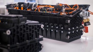
Figure 3. Gate centrally located inside a battery pocket, which eventually will be hidden with a removable cover. |
The example above shows a gate location centrally located for uniform material flow and hidden by a removable battery cover. This is one method of locating gates on cosmetic surfaces that solves two problems — optimizing material flow and providing a gate location that will not adversely affect part appearance.
|
Figure 4. Edge gate located along one edge of a cover. |
Edge gates, as shown above, are another means of providing an entry point for the plastic resin to flow into the mold cavity conventionally. This option is suitable if the wall thickness permits easy flow throughout the part without undesirable flow marks, warpage, splay, or undesirable shrinkage. The irregular surface in the area of the gate, which is typically removed by clippers, must also be considered. Sometimes surfaces along the edge of the part must precisely fit a mating piece. In such cases, the gate area must be post-machined to fit properly.
|
Figure 5. Gates located within open features. |
Gates are often located in open features such as windows or voids where other parts are inserted. If the edges of the part are critical for mating to another part or are cosmetically important, the designer must specify that the gate vestigial be machined to their specifications. Otherwise, the remaining material could interfere with mating parts or be cosmetically unacceptable.
|
Figure 6. Gate marks can also be covered by another part, as shown in this example. The handle covered the gate vestigial, thus eliminating costly post-molding machining operations. |
Gate remnants are often covered by another part, as shown above, or by labels. If a label is applied, you want to be sure the gate lies below the surface of the part so the label can easily be applied.
Choosing reverse ejection
If there are no good options for locating a gate on the outer cosmetic surface, reverse ejection may be considered — it should be the last option but may be the only choice. In reverse ejection, the mold is oriented such that the cavity side of the part (outer surface) is placed on the moveable platen and the core is mounted to the fixed platen. Material is injected directly into the core side (inside wall) of the part. Ejector pins are also located on this half of the mold. The part is ejected by attaching bars to either side of the moveable platen. As the moveable plate retracts, the bar engages with the knockout plate, moving the ejector pins forward and ejecting the part. The image in Figure 7 illustrates this method.
|
Figure 7. Reverse ejection. |
A few plastic part designers specify the specific gate location and gate design based on mold flow analysis. Since designers are not responsible for molding the parts, it is my opinion these details should be addressed by molders and tool builders. However, designers should be aware of the type of gate and its general location based on the reasons previously cited. The specific details should be mutually finalized between molders and part designers.
About the Author(s)
You May Also Like