Low levels of contaminants may hide the answer when common analysis tools are applied.Transparency is a highly valued property in plastic materials for a number of industries. In order to achieve good light transmittance, amorphous materials are generally used, since the presence of a crystalline structure contributes to the refraction of light. This diminishes light transmittance.
June 1, 2009
Low levels of contaminants may hide the answer when common analysis tools are applied.
Transparency is a highly valued property in plastic materials for a number of industries. In order to achieve good light transmittance, amorphous materials are generally used, since the presence of a crystalline structure contributes to the refraction of light. This diminishes light transmittance.
|
The light transmittance of some semicrystalline polymers can be improved through additive technology. Polypropylene (PP) is probably the most notable example of the use of these additives, and clarified PPs have been in existence for some time. The very low-density polyethylenes that can be made with metallocene catalysts will also exhibit improved clarity due to a decrease in the degree of crystallinity.
Less well-known are reasonably clear semicrystalline grades of nylon 6. These are not to be confused with amorphous nylons, where the chemistry of the polymer chain has purposely been altered to prevent crystallization from occurring. Amorphous nylons are truly transparent and will not crystallize under normal molding conditions.
The “clear” semicrystalline nylon 6 materials rely on rapid cooling rates and thin-walled designs. If the walls exceed thickness of more than 1-1.5 mm or if the mold temperature is raised, these materials will begin to exhibit the haze associated with crystal formation. Polymethyl-pentene, a little-known semicrystalline resin, can be molded with very low haze levels due to the extremely low density of the polymer.
But amorphous materials are inherently clear, and users of the materials expect good light transmittance and negligible haze levels to be part of the property profile. When these materials are molded into parts that exhibit haze, it is considered a defect and is usually attributable to contamination. Successfully identifying the contaminant can be deceptively challenging. The loss of desired clarity is usually obvious, but the amount of contamination needed to reduce light transmittance and create haze can be extremely small. This can make detection difficult despite the obvious nature of the defect.
Loss of clarity can come from several causes. First, the contaminant itself may be translucent or opaque. If polycarbonate or general-purpose polystyrene (GPPS) becomes contaminated with even a very small amount of polyethylene (PE), the molded part will become hazy. A less obvious cause is the mixing of two clear materials. GPPS mixed with acrylic produces a nearly opaque part because of the dissimilar refractive indices of the two materials.
Finally, there are amorphous materials that have the ability to crystallize under certain conditions. Perhaps the best-known example of this is PET polyester. PET is one of those materials that typically are slow to crystallize unless additives are incorporated to nucleate the polymer. Amorphous PET is clear and tough and will soften at the glass transition temperature, usually near 80°C. However, if the material is heated to temperatures of 120-130°C, the product will begin to develop a haze that is caused by crystal formation.
Theory vs. practice
If we assume that the cause of haze and loss of clarity is contamination, the task of the analyst is to identify the contaminant. Traditionally, the workhorse tools for identifying contamination in plastic materials are infrared spectroscopy (FT-IR) and differential scanning calorimetry (DSC). Both techniques are useful, but like all test methods, they have their limits.
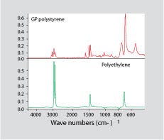
Figure 1. Infrared spectrum for general-purpose polystyrene (top) and polyethylene (bottom).
|
FT-IR produces a fingerprint of a material according to the types of chemical bonds present in the compound. In order for a contaminant to be detected by FT-IR, the contaminant must have a spectrum that contains absorption peaks that do not coincide with those of the contaminated material. Figure 1 shows an infrared spectrum for GPPS on top and a spectrum for PE on the bottom. Very small amounts of PE will produce haze in GPPS. However, PE has a very simple infrared spectrum that contains no absorption bands that are not also present in PS. Consequently, traces of PE will hide behind the more detailed spectrum of the PS. If the PE is present at a significant level, it may be possible to detect it analytically by subtracting the spectrum for pure PS from that of the contaminated material. In theory, this should leave a spectrum for the PE.
But as Yogi Berra once pointed out, “In theory there is no difference between theory and practice; in practice there is.” FT-IR typically has detection limits in the 1-2% range unless the substance being studied is a very strong IR absorber, such as water. This is why, for example, isobutyl rubber and chlorobutyl rubber are indistinguishable by FT-IR. The chlorine content of commercial chlorobutyl rubber is just slightly more than 1%. So despite the fact that chemical bonds are present in chlorobutyl that are not in isobutyl rubber, FT-IR cannot provide a distinct delineation between the two materials because the concentration of chlorine is too low to provide a measurable response. The small amounts of PE that can cause haze in GPPS can easily be less than 1% and therefore can escape detection by FT-IR.
However, PE is semicrystalline. Therefore, it has a melting point. This makes it ideal for detection by DSC. The strength of the melting endotherm for PE is very strong, while GPPS exhibits only a glass transition by DSC. Therefore, PE levels of tenths of a percent should produce a measurable melting point in the DSC scan. While this is an order of magnitude improvement in the detection limit, even this technique often fails to find the solution to a visually obvious problem.
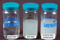
In cases like this, it is typically necessary to isolate the contaminant from the rest of the material in the part so that a positive identification can be made. This is effectively accomplished by dissolving the part in a suitable solvent. The good news here is that amorphous materials are less solvent-resistant than semicrystalline ones. Therefore, a solvent can frequently be selected that will dissolve the amorphous polymer such as PS but leave the semicrystalline component as a precipitate. Figure 2 shows a picture of different acrylic samples dissolved in methylene chloride. The jar on the left contains a material that shows no evidence of contamination, while the samples dissolved in the other two jars show possible problems.
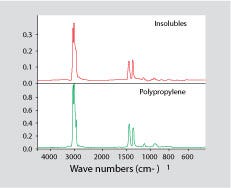
Once the primary polymer is in solution, the material can be filtered. The dissolved polymer will pass through the filter while the contaminant contributing to the cloudy appearance should be trapped. It can then be dried and identified, usually by FT-IR. Figure 3 shows a spectrum for a contaminant isolated from some parts molded from GPPS that exhibited a cloudy appearance. Each part weighed more than 30g, but four of them dissolved in methylene chloride produced only 60 mg of filtered contaminant. This constitutes only 0.05% of the material. However, once separated from the PS, it was readily identified as PP. Neither FT-IR nor DSC on the as-received part provided an answer to the problem.
Cloudy results
It is not always this easy. Some amorphous polymers are more solvent-resistant than others. PET polyester, for example, requires the use of much more aggressive solvents such as a chlorinated aromatic compound or even fully fluorinated alcohols such as hexafluoroisopropanol (HFIP). These are not for the faint of heart. In addition, because the analyst does not know the identity of the contaminant, it is possible that the solvent used to dissolve the polymer may also dissolve the contaminant. Visual inspection of the solution is important here since the objective is a clear solution and an isolated filtrate. If the solution remains cloudy, then the chances are quite good that the contaminant is still in solution. In these cases, it may be necessary to introduce a weaker solvent that keeps one polymer in solution and allows the other one to drop out.
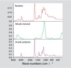
The offending material may not always be another plastic. Figure 4 shows a spectrum for the contaminant found in one of the jars shown in Figure 2. In this case, most of the contaminant turned out to be a silicate-based material such as calcium or sodium silicate.
The lesson here is that the familiar techniques used to solve particular problems often fail when they are applied to situations where contaminants may be present at low levels. When these standard methods fail to produce an answer, often the project is closed without producing a satisfactory solution. If a contaminant cannot be identified, then the manufacturing operation has no opportunity to find a root cause and prevent it in the future. However, with some knowledge of chemistry and some creativity, these elusive problems of trace contamination are solvable.
About the Author(s)
You May Also Like


