A robust process is the Holy Grail of injection molding—it keeps on making good parts over and over again. Achieving it is also a process. This two-part article lays out the process from start to finish. —Suhas Kulkarni
May 19, 2009
A robust process is the Holy Grail of injection molding—it keeps on making good parts over and over again. Achieving it is also a process. This two-part article lays out the process from start to finish. —Suhas Kulkarni
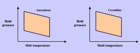
Qualifying a mold and part involves six steps: the viscosity study, the pressure drop test, the cavity balance determination, the process window study, the gate seal study, and the cooling time study. The fourth item, a process window study, provides information about the limits of the chosen process parameters between which acceptable parts can be molded. Typically, the window must be developed with hold pressure vs. melt temperature for amorphous materials and holding pressure vs. mold temperature for crystalline materials (Figure 1).
|
Within these limits (or inside this quadrilateral), the molded parts are free of cosmetic defects. For example, hold pressures above the top line may result in flash and below the lower line may result in sinks or shorts. A large process window is always desired to reduce the possibility of defects. A molded part that has shorts and flash is an example of “no process window.” A robust process is one that is set in the center of this window, which ensures that the natural variation in the process will still yield acceptable parts.
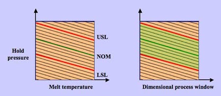
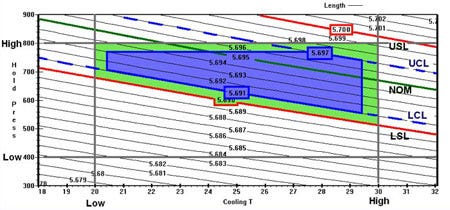
The technique above ensures aesthetic acceptance of the part. The center of the window would be a perfect process if the parts molded with these conditions had nominal dimensions and if the upper specification limit (USL) and the lower specification limit (LSL) were both contained within this window. Therefore, we must study the effect of both processing parameters on the dimensions of the part. The technique of design of experiments (DOE) can be used to perform such a study. Outputs from DOE include dimension contour plots, lines that describe the process conditions to achieve a certain dimension. Figure 2 shows a contour plot. The DOE studies must be carried out at the four corners of the process window where the parts are aesthetically acceptable. (Find more detail on DOE in Part 2 of this article.)
From the plot, it is evident that dimensionally acceptable parts now lie within a window that is smaller than and is a subset of the window previously developed. The previous window is called the aesthetic process window (APW) and the subset window above is called the dimensional process window (DPW). Figure 2 incorporates the upper and lower specification limits and shows the DPW generated from these limits.
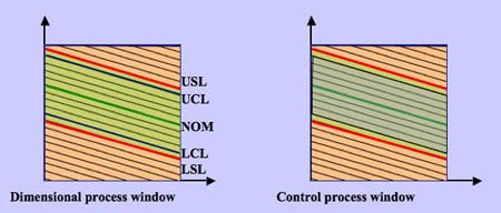
We now can take this concept a step further and incorporate process capability into the DPW. Control limits can be set based on the variation in the process and the dimensions. This is called the control process window (CPW), which takes into consideration all the naturally caused variations and provides the working windows. Figure 3 incorporates the upper and lower control limits and shows the CPW generated from these limits.
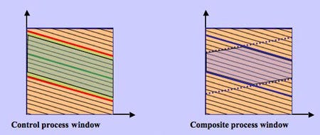
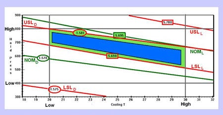
Overlaying multiple dimensions on this window makes the actual working window even smaller and the result is the composite process window (CoPW) shown in Figure 4.
All of these concepts, defined in the box at the bottom of this page, were applied to a part that was checked for length and diameter. Results are shown in Figures 5 and 6.
Setting alarm limits and tolerances
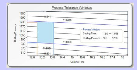
Alarm limits and tolerances are often confused with each other. Alarm limits are boundaries that are set on an output of the molding process, whereas tolerances are those that are set on the process settings. For example, in Figure 7, with a cooling time of 13 seconds (and a tolerance of 0.5 second), acceptable parts can be molded between 915 and 1200 psi. These should be the working tolerances for the production personnel. Let us assume that the cushion value at 915 psi is 0.23 inch and at 1200 psi is 0.18 inch. Then the alarm limits must be set on the cushion values with a low of 0.18 and a high of 0.23 inch. The concept can be taken to other outputs such as cavity pressure that is the final and most effective way of measuring part quality.
Overlaying the various windows generated during the mold qualification process displays the working areas of the molding process. Although mold qualifications using process engineering studies and DOEs are routine, there is an absence of a method of correlating the data from the two techniques. The two techniques each provide important data, but combining them provides a very clear understanding of the capabilities of the mold and the molding process.
Wide process windows provide an opportunity to run successful molding operations. Some would argue that the window gets smaller and smaller as the number of dimensions and cavities increases. Unfortunately, that is the reality, though it has been a hidden truth. This is the primary reason most companies have only one approved process sheet. The alarm limits and tolerances are usually set based on past molding experiences. Instead, these must be set based on the experiments performed and the results obtained from them. Understanding the sensitivity of the part quality to these factors gives an insight to setting the process parameter tolerances during molding.
Having multiple dimensions and multiple cavities makes the windows smaller and smaller. This further pleads the case for a well-built mold and parts with practically defined tolerances. Concurrent engineering principles and practices become important. A robust process requires less human intervention. The frequency of inspection can be reduced. Upfront planning and a disciplined approach to process development are therefore imperative to the efficiency of the production run and the profitability of the operation.
Suhas Kulkarni ([email protected]) is president of Fimmtech, a consulting firm that specializes in services related to injection molding. He has developed custom software called Nautilus that aids the complete process development routine based on Scientific Molding principles and Design of Experiments. Visit Suhas at NPE in booth S9024.
Read Part 2, “Scientific Molding and Design of Experiments: What comes first.”
Definitions Aesthetic process window (APW): The limits between which an aesthetically or cosmetically acceptable part can be molded. Dimensions are of no concern. |
About the Author(s)
You May Also Like
