By Design: Part design 104 — Internal voids
Though the desirability of maintaining a uniform wall thickness on injection molded parts has already been discussed in this series, there are many facets to this issue. As previously mentioned, the failure to provide a constant wall thickness can lead to sink marks that can then result in molded-in stress and appearance problems. This article will focus on internal voids, another problem associated with nonuniform wall thicknesses and abnormally thick walls.
September 2, 1999
Though the desirability of maintaining a uniform wall thickness on injection molded parts has already been discussed in this series, there are many facets to this issue. As previously mentioned, the failure to provide a constant wall thickness can lead to sink marks that can then result in molded-in stress and appearance problems. This article will focus on internal voids, another problem associated with nonuniform wall thicknesses and abnormally thick walls.
Internal voids have many things in common with sink marks, as both can be the result of a localized increase in mold shrinkage. However, voids are especially troublesome in transparent parts, where they can be easily detected by a buyer's quality assurance personnel and by end users-either of whom might jump to the erroneous conclusion that they are being cheated because the cavity was not completely filled with plastic material.
Parts molded in opaque plastics or colored materials are less of a problem, as the voids are hidden. Still, regardless if they can be seen or not, internal voids are indicative of other problems, and depending on how a part is loaded, they may or may not affect the part's physical strength.
Creating Voids
An internal void in a thick section indicates that there is more mold shrinkage around the void than in the surrounding area. An increase in mold shrinkage in thick sections is the most common cause of internal voids, but they can also be caused by nonuniform thicknesses and/or reverse melt flow.
|
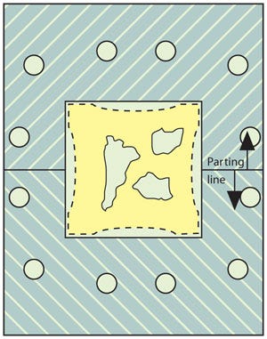
Figure 1. Mold shrinkage is depicted here by the broken line just inside the cavity. The sharp corners of this mold create nonuniform wall thickness, leading to sink marks and the possibility of internal voids. |
The molded part and a portion of the mold shown in Figure 1 depicts mold shrinkage as the broken line just inside of the cavity. As described in the last column, the large sink marks are the result of cooling and shrinking, or contraction of the mass of material in the center of the part. The maximum shrinkage is located halfway between the corners. The reason for this is that the sharp corners are thinner than the rest of the part. The tips of these corners are also being cooled from both sides. The corners solidify and regain their strength while the remainder of the part is still hot and soft. Continuing shrinkage in the center of the part then pulls the soft material between the corners inward, creating sink marks.
With a wall thickness of .250 inch or greater, the molded part shown in Figure 1 will also have a propensity for internal vacuum voids. At this thickness the flat surfaces between the corners become solid while the center of the part is still hot. The center of a thick-walled part such as this will continue to shrink, or contract, long after the outer surfaces have regained enough strength to resist any further deformation. When this happens, continued shrinkage in the center of the part creates an internal vacuum that draws moisture, or volatile gas, out of the plastic material to create internal vacuum voids (shown in Figure 1). If the part is cooled quickly in a cold cavity, the outer surfaces of the part will regain strength sooner, encouraging the formation of larger voids.
The higher mold shrinkage factor of semicrystalline plastic materials, which have definite solidification temperatures, makes these materials more troublesome in this regard than amorphous materials that solidify over a broader temperature range.
Internal voids can also be created by nonuniform melt flow. Some of the complex multifunctional parts now being molded cannot be designed with uniform wall thicknesses. Because plastic always seeks the flow path of least resistance as it moves through a cavity, and thick walls produce less resistance than thin walls, plastic material will flow through the thicker walls first. This flow pattern can allow the material to surround and trap air in a thinner portion of the part. This air normally shows up as a gas trap or a short shot. In some cases the trapped air can be swept into the center of the part producing an internal void. This type of void is frequently found in a location where two or more walls intersect.
Identifying and Eliminating Voids
It is sometimes difficult to determine whether an internal void was created by nonuniform melt flow or by a localized increase in shrinkage. It is important to be able to tell the difference between the two, as each requires a different solution.
Trapped air voids are usually located near the last area on a part to be filled, while vacuum voids are typically located in a thick section. Also, the gas in a trapped air void is encapsulated at a high cavity filling pressure, while the air in a vacuum void is at a negative pressure.
In the case of transparent parts, the difference between the two can be determined by reheating the part shortly after molding. The positive pressure in a trapped air void will cause the void to increase in size. The negative pressure in a vacuum void will cause the void to become smaller.
Trapped air voids can be eliminated through increased cavity venting or by changing the gating to eliminate backflow. A slower injection speed is also sometimes helpful. And while increased cavity packing pressure may reduce the size of a trapped air void, it will not eliminate the void. The best approach is to redesign the part to produce a cavity that fills uniformly.
Vacuum voids are normally the result of nonuniform or abnormally thick walls. Redesigning the part to eliminate these thick sections is the best way to eliminate vacuum voids. Still, a higher mold temperature that allows all of the surfaces to cool at a more uniform rate is sometimes helpful, and a larger gate that takes longer to solidify will allow more melt to flow into the cavity and compensate for the mold shrinkage.
|
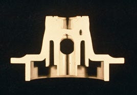
Figure 2. The injection molded ABS part shown here suffers from both sink marks and a vacuum void. A design modification gave the part a more uniform nominal wall thickness, solving these problems. |
Redesign Success Story
The injection molded ABS part shown in Figure 2 is blessed with both sink marks and a vacuum void. This heavily loaded part has two .800-inch-thick sections. During the cooling portion of the cycle, this part's inner surfaces, which are in contact with the cool cores, and the outside surfaces, in contact with the cool cavity, cool quickly and shrink in a uniform manner. The two thick sections near the top of the part take longer to cool, giving the plastic material in these areas more time to shrink and producing the two sink marks visible on each side of the part.
The thick mass of hot plastic material under each of the sink marks continues to shrink long after the outer surfaces have become rigid. This contraction develops negative pressure, which creates the vacuum void on the right side of the part.
Vacuum voids and sink marks of this type are indicative of an improper part design and/or inadequate molding procedures.
In the case of this opaque part, the internal void was not a problem. However, the sink marks were unacceptable. The sink marks and the void were eliminated by extending the coring further into the .800-inch-thick sections. This design modification gave the part a more uniform nominal wall thickness, which produced a better quality part that could be molded on a shorter cycle with less plastic material.
The part shown in Figure 2 also contains some corners that are generously radiused and others that are relatively sharp. As already described, these sharp outside corners encourage the formation of sink marks a
About the Author(s)
You May Also Like


