By Design: Part design 303 - Location of holes
In this bimonthly column, Glenn Beall of Glenn Beall Plastics Ltd. (Libertyville, IL) shares his special perspective on issues important to design engineers and the molding industry.
August 1, 2001
In this bimonthly column, Glenn Beall of Glenn Beall Plastics Ltd. (Libertyville, IL) shares his special perspective on issues important to design engineers and the molding industry.
|
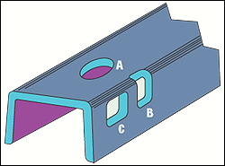
Figure 1. Holes A and B can be molded with a simple, straight opening mold. Hole C requires a more complex side-acting mold. |
The location of a hole on an injection molded part can have a significant effect on the cost and quality of a component. Hole location is dictated by the functional requirements of the part in its end-use environment. Within these limitations, the designer can still use discretion in positioning holes.
Every effort must be made to locate holes in line with the normal opening and closing movements of the mold. The round hole (A) in Figure 1 is parallel to the mold's opening action. In this position, the hole does not complicate the mold building or molding of the part. This is an ideal situation.
The square hole (C) shown in Figure 1 is located perpendicular to the direction of the mold's opening movement. This hole requires a side action to withdraw the core pin from the hole and allow the part to be ejected. Side-acting molds are more costly to build and maintain; they are normally larger in size than nonside-acting molds. These bigger molds sometimes require the use of larger molding machines, and larger machines cost more to operate. Side-acting molds do allow the molding of parts with more functionality. However, there is a price to be paid for this increased design freedom.
An alternate approach (B) to providing an opening through the sidewall is also shown in Figure 1. In this case, the material immediately above the hole has been removed. This hole can be molded with a projecting piece of steel in the cavity that seats on the core, eliminating the disadvantages of a side-acting mold.
The shape of the modified hole is not what the designer originally envisioned, but it may be an acceptable alternative. It is worth remembering that a simpler mold, with the minimum number of actions, is always the best mold. Figure 1 depicts one round hole and two square holes. The advantages of round vs. square holes were reviewed in my June 2001 By Design article (pp. 50-52).
|
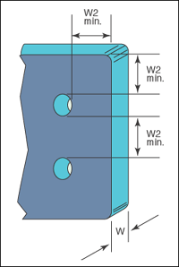
Figure 2. From an ease of molding perspective, the distance from a hole to the edge of a part or between holes should be two times the part's wall thickness. |
Hole Spacing
The distance between two holes, or a hole and the edge of a part, is dictated by strength and molding considerations. From an ease of molding perspective, the distance from one hole to the next, or to the edge of a part, must be at a minimum two times the part's wall thickness, and never less than the part's wall thickness (Figure 2).
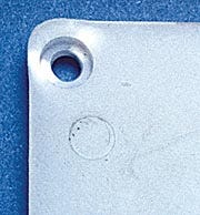
However, sometimes even this is not enough. The part shown in Figure 3 is distorted and stressed, despite the fact that the distance between the hole and the edge of the part is 1.6 times the part's wall thickness.
Also, the distance may have to be increased, depending on the strength of the plastic material and the forces acting on the hole. For example, a hole may be two wall thicknesses away from the edge of the part, which is satisfactory from a molding perspective, yet the strength of the material between these holes and the edge of the part may or may not be strong enough to resist failure.
Assembly Considerations
For instance, threaded fasteners in an assembly impose varying forces on the material around the holes. The angle on the underside of a flathead screw tends to expand the hole, imposing a high level of hoop stress on the material between that hole and the edge of the part.
A countersunk pan-head screw eliminates this hoop stress. However, countersinking the hole leaves only a thin wall of plastic under the screw head. Eliminating the countersunk hole makes the head of the screw more prominent, but the part's total wall thickness is available to support the load on that hole. There is, however, only a small area on which the screw head can seat. Placing a washer under the screw head distributes the load on the hole over more plastic material and minimizes creep due to compression of the material under the screw's head. The flathead screw and washer combination would be the most robust of these options, producing the strongest assembly. The flathead screw alone would be the least robust option.
The distance between closely spaced holes should be a minimum of two times the part's wall thickness. |
The distance between closely spaced holes should be a minimum of two times the part's wall thickness, as shown in Figure 2. Closer spacing impedes the flow of the plastic and encourages distortion of the holes. This distortion results from shrinkage of the plastic material between the holes. The two core pins that form the holes in Figure 2 prevent the whole part from moving to accommodate this shrinkage. In some instances, shrinkage pulls the plastic material away from the core pins, resulting in oval-shaped holes. This condition is more prevalent when the core pins are small and difficult to cool.
Greater distance between holes, such as six times the part's wall thickness, does not impede the flow of the plastic material. Mold shrinkage is distributed over a longer length of material between these holes, and there is less of a tendency to distort the holes.
|
Figure 3. The hole shown here is too close to the edge of the part. Shrinkage of the plastic material has distorted this hole and the thin wall around it. |
In Figure 3, where the spacing between holes or to the edge of a part is less than two times the part's wall thickness, the restriction to melt flow encourages weak weldlines in those locations. Weldlines between the holes and the edge of the part would significantly weaken that part. (Appearance and loss of strength problems created by weldlines were reviewed in my April 2001 By Design article pp. 48-50.)
Location Exceptions
The location and spacing of holes are important design details. The design guidelines just presented are worth considering. Judiciously applying these recommendations can produce a better-quality part that gets into production in minimum time. There are, however, exceptions. For example, electrical connectors must, of necessity, devote most of their available real estate to holes. As a result, the distance between holes and the outside edge of a connector is reduced to the minimum. In these cases, functional requirements dictate that good design practices be violated. These parts are, however, more difficult to mold. There is always a price to be paid for not following the established design guidelines.
Editor's note: A one-day seminar covering the part design details being presented in this series of By Design articles will be conducted by the author during the Appliance Manufacturers Conference & Exposition in Cincinnati, OH on Oct. 15, 2001. For registration information, contact Richard Babyak (440) 349-3060, ext. 205; fax (440) 498-9121; e-mail [email protected].
About the Author(s)
You May Also Like


