By Design: Part design 304 - Depth of holes
In this bimonthly column, Glenn Beall of Glenn Beall Plastics Ltd. (Libertyville, IL) shares his special perspective on issues important to design engineers and the molding industry. Design recommendations for the shape and location of holes in injection molded parts were presented in the last two articles in this series. Here we look at another design consideration: the depth of holes.
October 1, 2001
In this bimonthly column, Glenn Beall of Glenn Beall Plastics Ltd. (Libertyville, IL) shares his special perspective on issues important to design engineers and the molding industry.
Design recommendations for the shape and location of holes in injection molded parts were presented in the last two articles in this series. Here we look at another design consideration: the depth of holes.
Design engineers continue to push the limits of what can and cannot be molded. Modern injection molded parts are becoming both larger and smaller with no limit in sight. The entire roof of the Jeep Cherokee and the whole side of the Chrysler Concept Vehicles are molded as single parts. Small aerosol spray valves are now being produced in high-cavitation molds with orifice diameters of only .012 inch. And the advent of micromolding is producing tiny parts containing even smaller holes.
Holes are always smaller than the rest of a molded part. The core pins that form holes are, therefore, smaller and weaker than most other elements in a mold. But injection molding is a high-pressure melt flow process, and as the plastic flows through a cavity, it can bend core pins that extend into the melt flow path. The larger the length-to-diameter ratio of a core pin, the more susceptible it is to deflection.
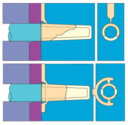
Figure 1. High-pressure melt impinging against a core pin can cause core deflection. |
|
Figure 2. High-pressure melt impinging on both sides of a core pin minimizes bending of the core. |
High Injection Pressure
The growing popularity of thin-wall molding has resulted in the development of injection molding machines with fast injection speeds and high pressures. Some of these new machines can achieve injection pressures up to 46,000 psi. The highest pressure in the cavity is at the gate.
If high-pressure melt coming through the gate impinges against a core pin, that core pin is subjected to a bending force. This situation is depicted in Figure 1. When the length-to-thickness ratio of such a pin exceeds 2:1 or 3:1, the pin can be bent by the inflowing melt.
As depicted, the melt normally flows faster on the side of the cavity closest to the gate. This condition produces more highly pressurized melt on the gate side of the core pin. With less melt on the opposite side of the core, the bending forces are magnified.
In spite of this adverse condition, parts such as hypodermic needle sheaths are being molded with length-to-thickness ratios of 18:1. Parts of this type do, however, require careful tooling and molding considerations. One technique widely used is to fill the cavity via two gates instead of one, as illustrated in Figure 2. With this gating approach, the core is subjected to the same forces on both sides. Needle sheaths are produced in fully automatic, 64-cavity molds, using a similar multiple-gate technique.
Logic would suggest that uniform melt flow on all sides of the core shown in Figure 1 could be achieved with a top center gate at the closed end of the cavity. The limitation of this approach is that melt doesn't always flow uniformly on all sides of a core pin. In other cases, the core pin is not in the exact center of the cavity. A lack of core and cavity concentricity encourages nonuniform melt flow and core pin deflection.
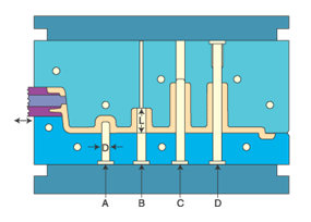
Mold designers have many options in gating a simple tubular shape, such as a hypodermic needle sheath. Complex shapes with multiple holes (Figure 3), however, are more challenging. With parts of this type it is difficult, or impossible, to gate the cavity in a location that provides uniform melt pressure on all sides of the core pins.
The freestanding core pin that forms the blind hole in Figure 3(A) is susceptible to being bent by the flow of the melt through the cavity. Its length-to-diameter ratio is limited to only 2:1 or 3:1. Changing the blind hole to a through hole, B in Figure 3, allows the free end of the core pin to be seated against the cavity. This supports the core and allows its length to be increased to 6:1.
Telescoping the core into a mating hole in the cavity, C in Figure 3, provides additional support. And a core pin anchored at both ends can have a length-to-diameter ratio of 12:1. However, one disadvantage of this approach is wear between the cavity and the free end of the core pin, which can result in flash and ongoing mold maintenance problems.
Molding a deep hole with two core pins, D in Figure 3, is another possibility. This approach eliminates wear between the core pin and the cavity. Holes produced in this manner can also have a 12:1 length-to-diameter ratio.
|
Figure 3. Supporting a core pin at both ends provides increased resistance to bending of the pin. |
Molding Considerations
It is the pressure of the melt that causes core pins to bend. Modern injection molding machines can profile the speed and pressure of the injection portion of the cycle. Profiling can be very helpful in minimizing the bending forces on long, small-diameter core pins. Applying full injection pressure only after all, or most, of the cavity is filled minimizes bending by producing more uniform pressure on all sides of a core pin.
All other things being equal, the hotter a plastic material is the easier it flows. Molding a plastic at its upper acceptable limit allows the cavity to be filled with a lower injection pressure. Reducing the injection pressure minimizes the bending forces on a core pin. Regrettably, a higher melt temperature also produces a longer molding cycle time. Molding at a high temperature can also result in thermal degradation of the resin.
Another option is to change to a plastic material with a higher melt index. The higher the melt index the lower the injection pressure required to fill a cavity. The disadvantage of this approach is that with most materials an increase in melt index results in a reduction in physical properties.
The core pins that form small holes also present cooling problems. Small-diameter core pins make it difficult to provide cooling water channels along the length of the pin. In many cases small core pins do not have direct cooling. These cores are cooled indirectly from the mold plates in which they are mounted. The larger the length-to-diameter ratio on a core pin, the more difficult it is to adequately cool the free end of the core. The proper cooling of core pins is an important mold design consideration, as cooling averages 70 to 80 percent of the molding cycle time.
The shape, location, and depth of holes in a molded part are dictated by functional requirements, but every effort must be made to minimize the length-to-diameter ratio of small holes. In those instances where long, small-diameter core pins cannot be avoided, designers should consult a knowledgeable molder and/or moldmaker as to what is practical.
About the Author(s)
You May Also Like


