Sign up for the PlasticsToday NewsFeed newsletter.
Sponsored By
Designing Screws for Profitable Injection Molding
September 2, 2002
9 Min Read
.svg?width=850&auto=webp&quality=95&format=jpg&disable=upscale "Designing Screws for Profitable Injection Molding")
Screw design is just one of the hundreds of details required for successful injection molding, but like many processing details in the industry, it only receives a small percentage of the attention it deserves. Unfortunately, this disrespect can cost molders anywhere from 10 to 30 percent in lost profits, and can also lower overall part quality. Given 15 minutes and data that shops already possess, it's not hard to prove there is money to be made with correct screw design.
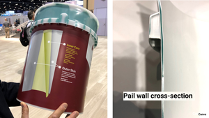
| The image at left shows a portion of the plastic in one flight from a metering zone of a screw. It contains black specks, or a carbon shower. |
|
Let's put screw design in perspective. While it can alleviate many processing problems, alone it will not solve all of them. In order to have an overall successful plastics application you must practice correct part design, plastic selection and handling, tool design and construction, and processing.
Screw design falls under the processing category. Specifically, it relates to melt temperature or uniformity. If you do not have uniformly melted plastic at the correct temperature coming out of your molding machine's nozzle, your chances of getting a part with dimensional stability are small to nonexistent. So let's discuss how a screw melts plastic.
The Anatomy of a Screw
It is important to identify the components of a screw?the feed, transition, and metering sections (see Figure 1, below)?and understand what happens in each. Normally, the feed section, which features constant, deep flights, is 50 percent of the flight length. The tapered flight depths of the transition section and the constant shallow flight depths of the metering sections each account for 25 percent. For example, a 20:1 length-to-diameter (L/D) ratio screw has 10 flights of feed, five flights of transition, and five flights of metering. It's recommended that the minimum L/D used in injection molding be 20:1. Shorter L/D ratios, like 16:1, tend to have melt uniformity problems even with proper screw designs.
|
As the granules travel through the hopper and feedthroat by gravity, they fill the deep flights of the feed section. The feedthroat should be warm?90 to 140F?to provide screw recovery time consistency (a consistent plasticating rate) and to prevent condensation of volatiles like residual moisture and off-gases from the resin. Moisture and off-gases can be a cause of splay. Often times, the feedthroat is run at too cool a temperature, but it's also important that the feedthroat isn't so hot that the granules stick together and block any gravity feeding. For best results, the feedthroat requires electronic temperature control. The use of cool tower water for temperature control is not acceptable for optimizing screw performance.
Technically, the purpose of the screw's feed section is to auger the granules forward to the transition zone, compacting and pressing out as much air as possible. There should be no melting within the first five flights. Sometimes the feed section does a bit more, with some heating occurring and some fines melting. As the granules are augered forward, the heater bands start the melting process by forcing the granules to stick to the barrel. Once this occurs, the real driving mechanism for melting takes over. It is the transition section that compresses the granules and forces them up against the barrel wall. As the screw rotates it shaves the melted plastic off the barrel wall and rolls it into the flight, forming what is called the melt pool. As it moves forward toward the nonreturn valve and screw tip, the melt pool gets larger while the solids bed gets smaller (see Figure 2, below). The diagram displays why it is important that the screw be smooth and polished with no nicks to allow the plastic to slide on it.
Eventually, the flight mostly contains melted plastic, or a melt pool as mentioned above, and a bit of unmelted or taffy-like resin that is the solids bed. About 50 to 90 percent of the energy needed to melt the plastic comes from this shearing action as the pellets change from solid to melt. This mechanical shear should not be confused with the shear rate developed when molten plastic in front of the screw is injected into the mold.
Consider the situation for a minute. Is the flight completely full? What is there to push this last bit of solids up against the barrel/wall and flight/land interfaces so all the plastic gets treated equally and uniformly? Some practical experience may shed some light on the answers.
A Closer Look at the Screw
What do you see when the screw is removed from the barrel? Note especially the rear of the flights at the end of the transition zone and beginning of the metering zone. About 95 percent of the time, you find a carbon layer at that location (see top item in top-left photo, above). Further, many processors report finding granules of a color they ran weeks before the most recent color processed.
These granules of carbon and previously run colors prove that the new melt coming down the screw does not push the rest of the melt out of the flight. This is why it takes so long to purge materials and change colors. We have unequivocal proof that this space behind the flights is simply dead space.
This is the same issue found in poorly designed nozzle tips and hot runner systems. Since this is dead space, the suggestion is to fill in this area with metal that has a large radius. Ideally, it should look like a farmer's plow.
The majority of the time the flights are not running full, and they have varying amounts of plastic in them depending on backpressure, viscosity, screw rpm, and other variables. Whenever you upset the status quo, such as running out of resin or changing backpressure or screw rpm, you can start a carbon shower. The carbon from the back side of some flights peels off and leaves black specks in the melt. Consider how many dollars are lost trying to purge black specks. Further, the solids bed can break up and get mixed into the melt pool, producing unmelted or partially melted plastic in the melt stream. These granules often move on to plug up the gate.
| Figure 1. The basic components of a screw are shown here. The feed section has constant deep flights and takes up 50 percent of the flight length. The transition section has a tapered flight depth and is 20 percent of the flight length, and the metering section has constant, shallow flight depths and is 25 percent of the flight length. |
| Figure 2. Shown here is the transition of plastic granules from an unmelted solids bed to a melt pool. As the plastic moves toward the screw tip, the melt pool gets bigger and the solids bed gets smaller. |
| Figure 3. This diagram illustrates good melt-uniformity screw design. The metering/transition section of the screw should be designed to tumble the melt gently and end in a slow taper. It should provide distributive mixing, but not dispersive or high-shear mixing. This is not an example of a mixing screw, or a high-intensity mixer. |
Achieving Melt Uniformity
Not all single-flighted, general purpose screws produce uniformly melted plastic. Let's define in general terms what is needed to melt plastic granules uniformly. Pooling data from work done by material suppliers, screw makers, and industry experts helps us identify the characteristics of a screw that produces consistent, uniform melt.
Let's define the "melt-uniformity" screw (see Figure 3, above). It isn't necessary to have a specially designed screw for each resin you process; that isn't practical for most molders. Having a single screw that provides uniform melt for several resins is possible, and you don't have to pay for uniform melt with slow plasticating rates.
The melt uniformity screw should have a significant radius on the rear of the flights at the end of the transition section and the beginning of the metering section.
It should have a mechanism that prevents unmelted or partially melted granules from getting through the system and into the molded part.
It should handle most resins, engineering and commodity, except those that are easily degraded.
Along with an extended wear life, it should not make the plastic too hot, and it should provide distributive mixing, but not dispersive or high-shear mixing. The high radius and greater melt homogeneity will help save money in the long run.
The screw material should be chemically inert, highly polished, and have sharp flight land edges. Its hardness should range between 50 and 65 Rockwell C. The screw's surface may be treated to aid wear slip and chemical resistance. The metal should be softer than the barrel metal by 3 to 5 Rockwell C points to prevent galling, since screws are often easier and cheaper to replace than barrels.
Resin should be run near the midrange temperature recommended by the resin supplier, and at backpressures in the 1000- to 1500-psi plastic pressure range. Backpressure is important to provide shot size volume consistency and fill the flights. Easily degraded resins should be run with less backpressure. Screw rpms should be set so that the screw is in the full shot position approximately 2 seconds before the clamp opens.
Case histories have shown that screws like this provide a return on investment in two to three months. The savings come from faster changeovers, less wasted plastic, stronger/less-visible weldlines, more consistent shrinkage, and stronger overall parts.
To learn more, talk to your screw supplier. The overall cost shouldn't be much greater than a standard screw if you're comparing similar materials of construction. The nonreturn valve should be the freeflow type with stepped angles and no sharp corners. The end cap nozzle body and tip should also have a smooth flow path, with no more than a .001-inch positive transition. Standard tips are not acceptable since they also have dead space.
Contact Information
Injection Molding Solutions, Midland, MI
John Bozzelli
(989) 832-2424; www.scientificmolding.com
You May Also Like