What does it take to remove bending and bowing in your part?My son was home from golf school and we decided to go out for breakfast. While we were out of the office, the UPS driver stopped by and, finding us gone, left a note telling us where to find the day’s packages. We got back in the car and headed for the UPS office on the northeast side of town. I opened the package and found one part and a runner system. Again, there was no note, but seeing the name on the return address, I figured I would be getting a call in a day or so.
June 2, 2010
What does it take to remove bending and bowing in your part?
My son was home from golf school and we decided to go out for breakfast. While we were out of the office, the UPS driver stopped by and, finding us gone, left a note telling us where to find the day’s packages. We got back in the car and headed for the UPS office on the northeast side of town.
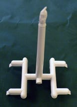
I opened the package and found one part and a runner system. Again, there was no note, but seeing the name on the return address, I figured I would be getting a call in a day or so.
|
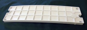
I did a quick visual review of the parts and found them to be suffering from a warpage condition that was causing a banana-type bow along the length of the part and sink on the side that didn’t have any ribs on it.
From the look and feel of the part, the material was certainly polypropylene. Part thickness was 0.250 inch and the ribs on the one side were 0.150 inch in height. This is a common design and often causes part warpage if everything is not done exactly right.
Next, I examined the runner and for this, I needed to dig into my briefcase for my measuring tools. The main runner was 0.250 inch thick, as were all the other runners. Whatever happened to making the runners the appropriate sizes based on the calculated size of the subrunner that feeds the gate?
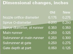
The runners were a modified trapezoidal design, all the same at 0.250 inch deep. What about the sprue diameters? We were looking at a two-cavity cold runner mold with a cold sprue dimension of 0.350 inch where the sprue attached to the runner and an O-diameter of 0.200 inch. The nozzle orifice diameter measured 0.175 inch.
I could tell just by looking that the sprue taper was excessive and was no doubt adding to the warp condition by requiring higher nozzle heats than necessary to get the material through the nozzle and into the cavities. Extra heat often is the cause of part warpage.
The sprue diameters should have been larger to pressurize the runner system. Even though this runner system was small, it needed the correct sizing and heats to keep these long, thick parts from warping or bowing.
I typically use 1.5° of taper on sprue bushings, which equals 0.0175-in/in. Will you find exceptions to this rule? Yes—I design in 3°-5° of sprue taper when working with soft materials such as polyurethane and thermoplastic elastomers.
|
This sprue was 3.250 inches long, and 3.250 multiplied by 0.0175 inch means the sprue O-diameter would be 0.057 inch smaller than the existing 0.350 inch where the sprue attaches to the runner.
Now we can see that the new sprue O-diameter of 0.293 inch would allow us to increase the general purpose nozzle orifice from 0.175 inch to 0.275 inch. This is a big difference and no doubt would allow the molder to reduce his nozzle temperature accordingly. Don’t forget, though, that dropping the melt temperatures excessively is not a good thing for PP since it is subject to brittleness when processed at temperatures lower than the material manufacturers recommend.
Would lowering the nozzle temperatures allow us to speed up the cycle time? Probably not, but it would open up the processing window and eliminate any tendency for the nozzle to string or drool. This is always good for the molding technicians, who already have too many fires to put out in a given day.
Runners, ribs, 
and radiusing
Next, I decided to take a few minutes to properly size the runner system. I always start with the subrunner that feeds the gate. With a part made of a crystalline material that’s 0.250 inch thick, the subrunner that feeds the gates should be 1.5 times thicker than the wall into which it feeds.
This calculation meant our trapezoidal subrunner needed to be 0.375 inch deep. I knew instinctively that was just too thick for these short subrunners. I could see this was going to be a trial-and-error situation, so I mentally reduced this subrunner depth requirement from 0.375 inch to 0.275 inch. This was thicker than the part wall by some 0.025 inch, but not so big that the system would end up with excessively large runners that we would regret later. The runner connecting both of these short subrunners/subgates to the one attached to the short main runner also would be 0.275 inch deep.
|
For the subrunner attached to the main runner, I stepped up the depth by 0.025-0.030 inch, and that meant the main runner would be 0.325 inch.
It was helpful to have two rectangular subgates in one end of the part; they would enable the parts to be molded straight instead of warped or bowed. However, I could see that they were going to be a problem thanks to the shallow angle of their design. The subgates were 0.200 inch deep where they attached to the subrunner and 0.050 inch deep where the gate attached to the part.
It’s a mystery to me why someone would design a perfectly good rectangular subgate with such a shallow attachment point to the subrunner. Based on a 0.250-inch part thickness, the gate depth should have been half of that, or 0.125 inch instead of 0.050 inch.
It’s no wonder these parts were warping. They were being filled with adequate injection pressure, but the gate was freezing off quickly due to the thin design and before any packing material could be injected into the cavities. This meant the parts were being underpacked, and warping resulted. Once the subgates were properly sized, we could play injection and hold pressures like a violin, the part would be properly packed, and the warp would quickly disappear.
These initial changes would take care of the warp, but you probably know me well enough by now to expect that I would look for other problems.
I zeroed in on the ribs. Reaching for my medium point Holiday Inn ballpoint pen, I drew a line where ribs and part wall meet to see if I would get a single or double line. It was a double line everywhere I tested, which, of course, means the ribs were not radiused.
The proper radius for a part that is 0.250 inch thick is a 25% blending radius of 0.0625 inch. Going from zero to a 0.0625-inch radius would provide plenty of impact strength in these typically weak rib areas. Notch sensitivity is a critical issue when working with crystalline materials, and this corrective action would make a huge difference in the cracks I saw where the ribs attached to the parts.
Uh, wait just a moment . . .
The time had come to call the molder. My suggestions for corrective action were well received but I had to keep repeating myself because the molder kept telling me to hold on a minute while he called another toolmaker, molder, or engineer into his office. Of course, I had to bring each person up to speed from the beginning of our discussion as they were added to the group, but ultimately we were able to get everyone clued in on my suggestions. The molder said the changes would be made and he would call me if they had any more questions.
Eventually I received a package with some very well-molded flat parts that did not have any cracked ribs, along with several bags of fresh pecans from way out there in west Texas.
Troubleshooter’s 
notebook
Part/material: Polypropylene.
Tool: Two-cavity cold runner.
Symptoms/problem: Warpage along the part, sink, cracks near the ribs.
Solution: To eliminate pressure losses in the runner system, enlarge runner dimensions and follow graduated sizing; increase diameters of sprue and nozzle orifice to allow for cooler processing temps; deepen gate at the part to keep it from freezing off before pack and fill is completed; radius ribs for strength.
About the Author(s)
You May Also Like


