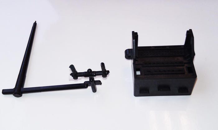
It is another day in the good old Central U.S. My dog Jake has been on his walk this morning and the big truck has delivered a small box full of parts for me to review. As often is the case, there is no note from the molder, but I have seen these particular parts in the past.
September 7, 2011
It is another day in the good old Central U.S. My dog Jake has been on his walk this morning and the big truck has delivered a small box full of parts for me to review. As often is the case, there is no note from the molder, but I have seen these particular parts in the past.
|
The Troubleshooter: Bob Hatch |
The part is an electronic coupling used in the aerospace industry. The material is a flame retardant unfilled nylon and I would guess that the problem is surface appearance. Pretty straight forward and even though appearance is not usually a key issue for parts used in parts normally hidden from view, during installation this might be the one exception I have seen.
Unfilled nylon is one of the materials that needs to have small runners and gates for successful molding. The melt temperature requirements of nylons are pretty straight forward in that they need to be high enough to melt the plastic but not a lot higher because we do not want the material to become degraded.
Drying is important in that the inlet air temperature to the material dryer needs to be set at 190°F and the cubic feet per minute of airflow needs to be 150. Most new dryers tend to be work well; it is the older dryers that cause the trouble due to poor maintenance.
The part wall thickness averages .080"and the interior of the part is full of core pins. I also don't see a lot of properly radiused sharp corners and edges throughout the part but since I did not receive any cracked or broken parts with the samples, I will follow up in this area in phase 2 if necessary.
Eyeing the runners
The runner system dimensions are pretty good for nylon. The level 3 sub-runners that feed the gates are .100" deep near the gate and .110" deep as it gets closer to the 2nd level sub runner. The 2nd level sub-runner is .150" deep and the main runner is also .150" deep. All runners are trapezoidal in design and well radiused.
The sprue dimensions are .140 at the "O" diameter and .290" where the sprue attaches to the runner. The nozzle orifice is .100" and the vestige on the end of the runner suggests the molder is correctly using a reverse taper nylon nozzle.

Troubleshooter unfilled nylon part
The gate is difficult to measure but I came up with a .050" gate size. Since the gate mark on the part is smooth and the part is well filled and packed, I suspect the part is well molded.I checked the rest of the part and did not see any evidence of missing core pins or ejector pin knock out marks. I did see slight burning of the material around the final fill areas of the parting line; these indicate poor venting conditions of the parting lines in general and are a reason for poor visuals at the parting line on the surface of the part.
The rest of the part surface did have slight imperfections that appeared to be due to a plate-out condition often caused by additives and volatiles when they leach out of a material during injection. This particular surface condition is often caused when running the barrel temperature at a temp that is slightly on the high side.
What did the molding tech get wrong?
My guess is that the inadequate venting caused the molding technician to slow the injection speed down to avoid burns, and the resulting under-packed conditions resulted in the material barrel temperatures being raised to compensate. The plate-out condition followed.
The venting issue seemed to be the only problem with these parts. I will suggest that the toolmaker make all parting line vents .0005" deep, then go out .040" from the parting line and drop down into a .040" deep channel to atmosphere. The width of these vents on small parts needs to be .100" wide and installed at 2 vents per parting line inch. Then - most importantly - the vent lips need to be draw polished to a mirror finish to make them self-cleaning. The rest of the vent requirements in each cavity seemed to be well vented due to the lack of burns at each of these locations.
I placed a call to the molder and passed my suggestions on to him, and of course I sent a follow up e-mail to avoid any problems. We also discussed the problems with the economy, the weather and the best day of the week to go golfing in our respective areas.
He said he would pass my venting suggestions on to his toolmaker; if he had any questions, then he would get back to me. He called the next day with questions about the design of the vents that I had suggested. I referred him to several articles in my "On The Road With Bob Hatch" book that details venting in general and parting line vents in particular, and I also reminded that they already had a copy of this book in their own technical library. I went on to tell him that they could order another copy of my book from BobHatchOnLine.com if they wanted to have an extra book on hand.
A week later I heard from the molder again. He said they vented the mold according to my suggestions and the parts were running just like they used to.
About the author: Consultant Bob Hatch of Bob Hatch & Assoc. (www.bobhatchonline.com) has more than 45 years of experience finding solutions to processing challenges. Reach him at [email protected].
About the Author(s)
You May Also Like


