Sign up for the PlasticsToday NewsFeed newsletter.
Sponsored By
Film insert molding breaks into nonautomotive markets--with style
December 7, 1998
11 Min Read
.svg?width=850&auto=webp&quality=95&format=jpg&disable=upscale "Film insert molding breaks into nonautomotive markets--with style")
While the results can be attractive and functional at the same time, in-mold decorating requires some special know-how to make it work.
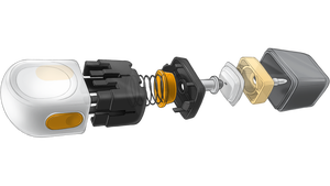
Figure 1. The bezel on this digital multimeter from Tektronix is molded in one shot thanks to film insert molding (FIM). It starts with a polycarbonate film that's decorated, thermoformed to shape, and then inserted in the mold. Molder Polycast worked for two years to develop and fine-tune the process for the bezel. |
It may not look like it at first, but the Tektronix TX Series True RMS MultiMeter (Figure 1) represents a small watershed for the injection molding industry. It is one of the first nonautomotive, handheld instruments to be decorated via film insert molding (FIM). This six-by-three-inch bezel is molded from polycarbonate injected behind a film of polycarbonate decorated with two colors and labeled. In one shot, molder Polycast (Tigard, OR) produces a finished part, which otherwise would have required the production of at least four separate parts, assembly of those parts, and post-mold decorating.
A digital multimeter is today's equivalent of what used to be known as a voltmeter. The multimeter takes a number of measurements including resistor, capacitor, voltage, current, and temperature. The bezel encloses the electronic guts of the device and includes a window to display data, buttons, and a function dial for selecting different operations. What makes the molding for the Tektronix multimeter so unique is the integration of the window and graphics in the press. Typically, the bezel is molded separately, possibly from a different material, and then decorated as needed. Then, finally, the window is attached and the part is complete.
Polycast employs about 44 people, runs 15 Cincinnati Milacron presses ranging from 28 to 400 tons, and serves the automotive and electronics markets. Tektronix, a longtime customer of Polycast, had previous versions of the multimeter's bezels molded in Taiwan but decided to bring production for the newest incarnation to the U.S. Development of the multimeter began two years ago. "For this project, we were involved from its inception," says Bernie Taylor of Polycast business development.
Tektronix, for its part, was looking to create a multimeter distinct not only in function but appearance as well. Steve Lyford, a mechanical design engineer at Tektronix, says the desire to use a larger window, multiple colors, and a 3-D-like bezel surface pushed the manufacturer to FIM. "In looking at what we tried to do, we just kept getting closer to FIM," he says. "It was the only way to do what we were trying to accomplish."
FIM: What It Is
If you've tried FIM before, you know it is not a process for the weak of heart or the short of time. Polycast, Tektronix, and label supplier Serigraph took two years to develop and fine-tune the FIM process and needed every day, says Taylor. If you're unfamiliar, FIM-or in-mold decorating-works like this, at least for the Tektronix multimeter application.
1. A film of polycarbonate is cut to shape and screen printed with the color and labeling required for the product. This includes the black and gray background with white and blue lettering on top in this part.
2. Next, a protective coating is applied. Lately, more companies, including Polycast, are opting to reverse decorate the film (underside decorating), using the film layer as the protective coat.
3. The film is thermoformed to the shape of the bezel, and holes are punched to accommodate the buttons in the multimeter.
4. The thermoformed film, called an appliqué, is inserted in the mold before injection. The mold closes and the polycarbonate (Bayer's Makrolon 2458) bezel is molded behind the decorated appliqué, which bonds to the bezel.
5. The finished part is picked out of the press by a robot, ready for assembly with the rest of the device.
Sounds simple, doesn't it? As you might guess, it isn't. Although the process has been honed to a degree of efficiency now, getting there meant clearing a few hurdles along the way.
Figure 2. Because of the variety of forces that act on the film, the edge of the appliqué is rarely straight. To compensate, Tektronix and Polycast dropped the edge below the parting line where it would be hidden by the mating half of the multimeter. |
The Challenges
Taylor says there were several technical challenges to using FIM with this bezel. Most of these were solved by trial and error. Before it cut a single mold, Polycast got an old bezel tool, modified it slightly, and started testing FIM. The technicians had to assess material compatibility, the effect of gating on the appliqué in the mold, and parting line considerations. The molder also had to ensure window clarity, keep the appliqué contamination-free, and maintain the legibility of the labels.
Chief among these challenges was legibility. Almost every process the appliqué endures-thermoforming, hole punching, molding-imparts to it some kind of stretching, pulling, or pushing. Each tug at the film increases the chance that the lettering will be stretched or distorted. Taylor says Polycast and Tektronix conducted a series of tests to determine just which process distorted which letters or symbols in which direction. "We then 'morphed' the text to accommodate the movement of the film and resin during the processes," he says. Actually, label supplier Serigraph did the morphing, but the goal is to intentionally distort the text when it's printed, expecting it to be "pulled" in a predictable manner to a readable state by the processes that act on it.
Another tricky aspect of the bezel involves the parting line and follows this thought from Taylor: "The technology of this time does not allow the appliqué to have a straight edge." That is because the appliqué starts life as a flat piece of polycarbonate film which is thermoformed, die cut, and then stretched again in the mold. These forces are so variable that producing an absolutely straight edge is extremely difficult. Plus, polycarbonate does not cut easily.
The idea is to hide the uneven edge of the appliqué. Tektronix and Polycast chose to wrap the appliqué down the sides of the bezel. This put the edge of the appliqué somewhere near the terminating edge of the bezel itself. By way of a patented tool design, Tektronix and Polycast dropped the edge of the appliqué past the parting line so when the bezel is mated with its second half, the jagged edge is hidden, preserving the aesthetic appeal of the part (Figure 2, opposite). "It was a major technical challenge for us," Taylor says.
Lyford says another challenge was making sure the edge of the label didn't get caught on the parting line of the mold; eventually the edges were folded back a little bit to prevent this from happening. "Like troubleshooting anything, it feels like peeling an onion," Lyford says. "Just when it seems you've fixed one problem, another is revealed." He also points out the holes in the bezel were die cut on the label and had to not only line up with cores in the mold but match the diameter of the cores as well.
Another first of the bezel, to everyone's knowledge, is the window. Lyford says it is the largest window ever molded with FIM. The big window is a major selling point for the multimeter as it allows the user to view readouts from several feet away. Polycast and Tektronix had to make sure the optical clarity of that window was not disturbed by the label molded on top of it. Also, any movement of the label in the mold could jeopardize window aesthetics. Again, trial and error was the antidote.
The final challenge was airborne dust, which naturally gravitated to the film, particularly once it was placed in the mold. Polycast uses a two-cavity mold to make the bezels and places the appliqué in the press via robot. Still, dust specks fell between the appliqué and the resin. Ultimately, says Taylor, the company opted to use a Hepa-filtered chamber that surrounds the press and keeps contaminants out.
The Upshot
The good news is that, thanks in part to what FIM allowed Tektronix to do, the company has a popular and distinct multimeter. K.L. Yeung, product marketing manager for handheld products at Tektronix, says customer studies show the multimeter is highly recognized and greatly appreciated for its large display. Also, the multimeter has an infrared interface that cannot have a direct metal contact. The all-plastic housing allowed this and makes the multimeter the first computer-calibrated unit of its kind-another feather in the cap.
Lyford says OEMs and molders considering FIM or in-mold decorating must brace themselves. "It took us a lot more work than I anticipated," he says. He recommends a partnership similar to what Tektronix developed with Polycast and Serigraph. "Pick partners who recognize that the total system can work better if each side can make changes to accommodate a successful part." Be prepared to be flexible, open-minded, and resilient. Fine-tuning FIM is a particularly fluid and dynamic process that doesn't always adhere to deadlines.
In-mold decorating: Taking the plunge
Unlike most decorating systems that are used after molding, in-mold decorating means a level of complexity most molders are not used to handling. Polycast's Bernie Taylor (see main story) says molders who want to start using in-mold decorating have to understand up front how much more responsibility it places on them. "With in-mold decorating, the molder buys the label and is responsible for the finished product," he says. "The label is an integrated part of the process."
With that in mind, IMM has explored the costs, requirements, and adjustments a molder must make before taking on and integrating this burgeoning and popular process into his or her operation. For answers and insight, we turned to Jan Livingston, group leader in research and development at Serigraph, the Wisconsin-based manufacturer of decorating systems, including the in-mold type.
Before using in-mold decorating, molders must accept the fact that, unlike traditional decorating methods, this process is performed in the mold. This introduces new variables to the cycle and requires a trial-and-error approach to develop a stable process. |
Applications
As popular and efficient a process as in-mold decorating has become, it is not the be-all and end-all of decorating. Livingston says parts best suited for in-mold decorating are those that are often the most difficult to decorate otherwise. She says parts with compound curves, deep draws, and lots of knit lines are often good in-mold candidates. "It's also very good when there are several colors to put down," she says, meaning more than two or three.
"At the same time, in-mold decorating doesn't always save money," Livingston says. "If a simple graphic of medium quality is acceptable, then simple pad printing may be preferable." Still, in-mold decorating almost always eliminates some sort of post-mold work, which saves money.
Machine, Material Adjustments
By introducing another variable into the mold, cycle time can take a hit with in-mold labeling.
Livingston says the effect depends on several things. The first is how the label is delivered to the mold. For large parts, like basketball backboards, manual placement is the only option and can add significantly to the cycle. For smaller parts, robotic or automatic insertion is possible, which may lengthen the cycle minimally. Beyond the act of delivering the label, inserts in the mold can act as an insulator, making for a longer cooling stage. Labels range from .003 to .040 inch thick.
Cycle time aside, the biggest mechanical and engineering challenge of using in-mold labeling is fine-tuning gate placement. This aspect of the system constitutes the biggest tooling change. "You have to be concerned about gate placement," Livingston says. "You have to think about where the ink contacts plastic. The hot resin in most cases will just melt the ink on the label." Basically, she says, no gates should be on the decorated surface.
In-mold decorating's big upside is that odd contours, curves, and crevices can be decorated. Also the decoration is permanently bonded to the molded surface. And if you use reverse decorating, a natural barrier separates the decorated surface from the wear and tear of everyday use. |
But gates can't just be moved at will. Molders still have to consider flow properties of the part itself and how that flow will affect the orientation of the label. "Aside from not gating on a printed surface, you have to use the natural flow of resin to hold the label in place," says Livingston. Unfortunately, determining the proper gate location is still as much art as science and requires a fair amount of trial and error before an acceptable part can be attained.
The Mental Hurdle
The costs of mechanically accommodating in-mold decorating, although potentially time-consuming, are relatively minor. Livingston says the greatest expense is in education. "The biggest cost of implementing in-mold decorating is in the learning curve to mold differently," she says. Injection speeds may change, cooling times may vary, resin may behave differently. Some of it is counter-intuitive. "We don't always know why material behaves the way it does," remarks Livingston.
She says anyone contemplating in-mold decorating needs to be able to "change his mindset" to mold differently. She says to allow time to experiment, test, and analyze results. Allow time for trial and error and be ready to learn. "Most people," she says, "underestimate the learning curve."
You May Also Like