By Design: Their first injection molded part
Metal-to-plastic conversions can result in overdesign.The world is experiencing a growing shortage of water. Anything having to do with conserving, reclaiming, and purifying water is a growing market. I don’t know much about the water treatment industry, but I can spot a poorly designed plastic plumbing component.
August 4, 2010
Metal-to-plastic conversions can result in overdesign.
The world is experiencing a growing shortage of water. Anything having to do with conserving, reclaiming, and purifying water is a growing market. I don’t know much about the water treatment industry, but I can spot a poorly designed plastic plumbing component.
This is the story of a successful water treatment equipment manufacturing company that rested on its laurels. Its equipment was the best in the industry and management saw no reason to go to the expense of introducing new products. As a market leader, it remained profitable by increasing its prices. Meanwhile, its competitors prospered by reducing costs.
|
A declining market share prompted the company to take action. It found ways to streamline and automate its manufacturing and distribution operations. A review of competitors’ offerings indicated an opportunity for some new products. These studies also indicated that the competitors were using a lot of plastic components. It was surmised that the use of plastics allowed the competition to minimize costs, so the company authorized the development of a line of products that used plastics wherever practical. While this was a logical decision, it created a problem.
First conversion
This market leader had a long and successful history of manufacturing metal products. Many of its components were screw-machined or cast and machined brass. The company’s engineers were genuinely concerned about the strength and reliability of plastic materials. The chief engineer chose and personally designed the company’s first injection molded part—a water flow control and mixing venturi. He also specified a 20% glass-fiber-reinforced Noryl (polyphenylene oxide). This was a good choice, as Noryl is widely used in plumbing applications.
These were major changes for a part that heretofore would have been cast and machined brass. The chief engineer was so concerned about this plastic part that he came to my company to produce preproduction molded parts for testing. He said that this was his company’s first injection molded plastic part. If there were any problems, it would be another generation before the company would try another plastic component.
|
He explained that this was his first experience in designing a plastic part and he wanted my advice on the part design. I reviewed the drawing and commented that it was in better shape than what engineers normally produce on their first try. My only concern was why such a small part had a 0.315-inch wall thickness. He said the part had to withstand an internal 250-psi impact-type pressure test.
I did a quick calculation and pointed out that a 0.138-inch-thick wall would withstand that pressure with a 50% safety margin. He told me that he had read that IM parts contained molded-in stress and weak weldlines on fiber-reinforced parts. He said he needed the thick walls in order to duplicate the performance of a brass part.
Overdesign issues
They are not always right, but it is never prudent to start an argument with a customer, especially the customer’s chief engineer. I agreed to proceed with the thick walls on a best-effort basis. I did, however, point out that the 0.055 ±0.002-inch tolerance on the small end of the venturi could not be guaranteed.
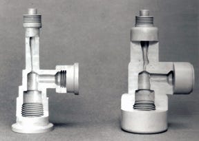
A prototype mold was built and sampled. Molded parts passed the pressure tests, but the venturi did not have the required metering function. The venturi hole had distorted into an oval shape measuring an average of 0.054 by 0.066 inch. The sectioned part on the right side of the figure shows the deformation of the tapered hole leading down to the venturi. These deformities are caused by the increased wall thickness where the side port joins the part’s main vertical body.
It is interesting to note that the thickness of material is the same above and below the side port, but no deformation is evident below the side port. This difference can be attributed to an inability to cool the small core pin forming the venturi.
During the cooling portion of the cycle, the outer surfaces of the part in contact with the cold cavity cooled quickly and stopped shrinking. The same thing happened on the inner surfaces in contact with the larger side port and lower threaded core pins, which could be adequately cooled. The same could not be said for the surfaces in contact with the relatively long, small-diameter core pin that formed the venturi. The plastic material around the venturi core pin was the last location of the part to cool and stop shrinking.
Continuing shrinkage in the center of the thick sections created a negative internal pressure. This negative pressure pulled the still hot and soft material away from the venturi core pin to create the out-of-spec, oval-shaped hole and the deformation just above the venturi. That negative pressure also created a multiplicity of small voids around the venturi.
The size of the gate was increased; however, no combination of time, temperature, or pressure was capable of producing an acceptable part. The thick walls and the inability to adequately cool the venturi core pin created a part with uncontrollable shrinkage and deformation.
A successful redesign
In order to salvage the project, the chief engineer reluctantly agreed to try molding the part with the wall thickness reduced to 0.146 inch. The actual venturi was now a round hole measuring 0.055 ±0.0005 inch. There were no irregularities along the length of the taper leading to the venturi. This eliminated the turbulence that interfered with laminar flow leading into the venturi.
The part went into production as a four-cavity, automatic unscrewing mold. The thin-walled part weighed 25.9g less and ran on a 47-second shorter cycle than the original design. In the two or so years that I oversaw the project I never heard of any of these thinner-walled parts failing the company’s pressure tests.
Many metal parts are overdesigned. It is always better to design for the actual loads than to duplicate the strength of the metal part being replaced. The ideal thickness is the thinnest wall that will satisfy the application.
Sooner or later engineers design their first plastic part. Novice plastic part designers would be well advised to heed the advice of an experienced plastician.
About the Author(s)
You May Also Like


