The Troubleshooter, Part 114: Nylon remains a mystery to toolmakers and molders alike
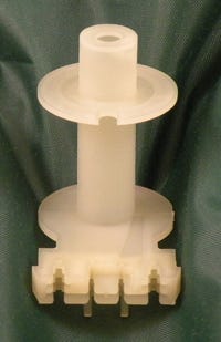
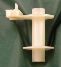
Turning down the nozzle heat to prevent nylon from drooling is a poor substitute for proper sprue and runner design.Guess what I got this month? A stretched-out runner with a couple of parts. The molder’s note complained about dimensions being on the short side of the tolerances, and the inside diameter of the center hole was often on the small side.
June 1, 2009
Turning down the nozzle heat to prevent nylon from drooling is a poor substitute for proper sprue and runner design.
Guess what I got this month? A stretched-out runner with a couple of parts. The molder’s note complained about dimensions being on the short side of the tolerances, and the inside diameter of the center hole was often on the small side.
|
It was no surprise that the sprue was much too small for the runner: Toolmakers like to undersize the sprue for nylon because they think they’re helping out the molders by keeping the nozzle from drooling. Crazy guys. The way to stop the nozzle from drooling when running unfilled nylon is to 1) dry it thoroughly in a desiccant-style hopper dryer and 2) use a reverse-taper nylon nozzle for unfilled PA.
The main runner diameter measured about 0.240 inch full round, and the full-round runners were a good choice—in fact, they’re good for any material. The subrunners were unusual in that they were 0.195 inch where they attached to the main runner but only 0.160 inch from the middle of the subrunner out to the gate. A runner does not need to be reduced in diameter unless you are splitting the flow into two different gate locations from a single runner.
|
Speaking of gates, they were all 0.060 inch in diameter and fed right into the 0.060-inch-thick disk located on the top of the part. The gate width was 0.090 inch and the land was 0.020-0.030 inch (it was hard to tell because somebody clipped the gates pretty close on these samples).
The sprue O-diameter was 0.165 inch, the sprue measured 0.260 inch where it attached to the runner, and the nozzle orifice measured 0.135 inch on the small end of the sprue. From the residue on the end of the sprue it appeared that a general-purpose nozzle was being used instead of a reverse-taper nylon nozzle.
The only part of this review that pointed to a problem was the undersized sprue diameter. Everything else might have been outside the rulebook, but it was unlikely that the sprue and runner were responsible for the problems.
Attention to nylon
I looked the parts over carefully, reviewed the sprue and runners again, and decided all the problems being mentioned by the molder could be attributed to his molding technicians running the nozzle heats higher than normal to accommodate for the undersized sprue bushing.
I looked at the processing sheet once more and noticed that the front zone was set at 520°F while the nozzle heats were 560°F—a dead giveaway that a flow restriction existed somewhere around the molding machine nozzle, possibly in the sprue bushing.
To size the sprue bushing correctly, we could recut the runner plate and make the main runner diameter smaller, such as 0.200 inch, or we could leave the main runner at 0.240 inch and increase the tapered diameter of the sprue so the sprue O-diameter was bigger than the main runner.
Ideally, when the main runner diameter is 0.250 inch, we make the sprue O-diameter 0.312 inch and the nozzle orifice diameter 0.275 inch. Nylon requires a lot of attention when it comes to making these large diameters work out. The nylon has to be dried extremely well and both nozzle heats and front zone heats have to be set at a temperature low enough to keep the nylon from stringing or drooling.
I went out on a limb and suggested that the front zone heat should be 520°F and the nozzle temperatures around 510°F. However, I urge caution with these heats because nylon is highly crystalline and you don’t want it freezing off in the adapter area or in front of the check valve.
The screw would create some shear heat there, plus there would be conductive heat from the heater bands, so the goal for nylon is to get close to the minimum temperatures recommended for that material without letting them get too low. Nylon 6 starts to freeze off around 475°F and nylon 6/6 stops moving around 500°F. Be sure you know the type of nylon you are processing and you should not have any problems.
That was about all I could do for this molder, other than standing beside the press with him so I could check the dryer operation, hoses, and temperatures, and also the waterlines to get rid of jumpers and quick disconnects.
I e-mailed the molder my two recommended changes—the sprue size and the type of nozzle. When he called a couple of days later, he gave me the good news: He was molding good parts again. All the dimensions fell into place, the inside diameter of the center hole was back where it belonged, and he was sending me a check with a little bonus for helping him out so quickly. I liked his attitude and the check didn’t hurt, either. Another day, another success.
The Troubleshooter’s notebook Part/material: Nylon. Tool: Four-cavity cold runner. Symptoms/problem: Parts were not meeting specified tolerances and the center hole was often too small. Solution: Increase sprue O-diameter from 0.165 to 0.312 inch; change GP nozzle to reverse-taper nylon nozzle. |
About the Author(s)
You May Also Like
