The Materials Analyst, Part 48: I can't believe it's not crystalline (Part 5)
October 1, 2001
|
This series of articles is designed to help molders understand how a few analytical tools can help diagnose a part failure. Michael Sepe is our analyst and author. He is the technical director at Dickten & Masch Mfg., a molder of thermoset and thermoplastic materials in Nashotah, WI. Mike has provided analytical services to material suppliers, molders, and end users for 15-plus years. |
We have slowly developed the principles behind the phenomenon of crystallization in polymers. Now it's time to take these lessons to the production arena and look at some solutions to problems in the real world.
The first one involves a gear produced in a 45 percent glass-fiber-reinforced PET polyester. PET is one of those materials that straddles the fence when dividing semicrystalline materials from amorphous ones. Water and soft drink bottles are testimony to the fact that PET can and does exist in the amorphous state. But with some creative nucleating chemistry and the help of some fillers, PET was launched as a semicrystalline engineering material in the late 1970s. The problem is that every PET supplier uses a slightly different nucleating technology. The most efficient ones produce a serviceable degree of crystallinity with a mold temperature of about 90C (194F). Other materials that may appear to be equivalent actually require mold temperatures of 110 to 120C (230 to 248F) to achieve the same performance.
Our client had been successfully molding a gear in one supplier's PET for a number of years. The nominal wall of the part was relatively thick at about 7 mm, and a useful part was being produced with a mold temperature of 70 to 75C (158 to 167F). The part was tested by thermal cycling from —40 to 85C as part of qualification.
When the application was switched to a new PET from a different supplier, parts began to fail at the upper end of the thermal cycling routine. When failed parts were examined it was discovered that the gear teeth were deformed. This was particularly puzzling since the PET gear, which was highly reinforced with glass, was running against an acetal gear that was unfilled. While the PET gear teeth were deformed, the acetal tooth form was perfect. How does a material with a melting point of 250C deform at 85C while a gear made from a material with a much lower melting point remains untouched?
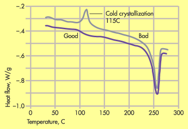
The answer lies in the poor crystallinity of the new PET. Figure 1 shows a DSC comparison of the molded part in the new and old PET. The strong peak near 115C in the bad part is evidence of the incomplete crystallization process during molding. The nucleation chemistry of the new PET was not as efficient as that of the old PET. As a result the degree of crystallinity achieved using the same molding conditions was significantly lower. While the melting point of PET is 250C, the glass transition temperature (Tg) is approximately 80 to 85C.
|
Figure 1. DSC plot of good and bad PET moldings show undercrystallized material in bad part. |
As we have already seen, in a poorly crystallized system the Tg becomes a potential limiting condition for elevated temperature performance. The edge of the tooth form was substantially thinner than the rest of the part and therefore it cooled much faster than the rest of the part. When this was combined with the slower crystallization rate in the new material, the result was a part with a substantially lower degree of crystallinity. Suddenly a good application had turned into a problem. A higher mold temperature was needed to develop the required degree of crystallinity in the new material, and this difference in processing requirements was not apparent without careful analysis. The additional expense of employing oil or electric heat and the prospect of a longer cycle that might result outweighed the savings in cost per pound that was realized by switching materials.
It is important to note that this type of problem is highly dependent on wall thickness. DSC samples tend to be very small, about 10 to 20 mg, and the sample size often captures only what is happening at a particular location. A gear tooth quickly thickens as it tapers back to the nominal wall, so detection of a localized problem demands careful sample preparation. The supplier of the new PET had run the same DSC tests and had failed to find the problem simply because of a difference in sample location.
Annealing: Use With Care
The good news is that in a case like this where most of the part is properly crystallized, annealing can save bad parts. Annealing is often thought of as a stress relief technique for amorphous materials, but if parts molded from a semicrystalline material are heated to a temperature above the glass transition, the motion required for crystallization begins again and additional material organizes into crystals. For the sake of efficiency the annealing temperature is usually set well above the Tg and is ideally higher than the end use temperature of the product.
In molding, parts cool from the outside in, so the skin of the part is the area most likely to lack the necessary crystallinity. In annealing, however, it is the skin that heats up first so these areas can be fixed relatively quickly. Yet, the time-temperature routine for any given part is dependent on part geometry, the original processing conditions, and the resin system. In the case of the gears, 45 minutes at 135C (275F) was sufficient to correct the problem, saving thousands of parts that might have otherwise been scrapped.
Annealing, however, should not be undertaken lightly. Because it promotes additional crystallization, annealing can produce additional shrinkage and warpage. Annealing temperatures may also be aggressive enough to promote oxidation of some polymers, a chemical reaction that can result in discoloration and even embrittlement. In such cases the annealing process must be conducted in a fluid that shields the material from oxygen.
And there is another consideration in annealing that is often overlooked. Crystals that form during annealing are not as large or as perfect as those that form during cooling from the melt. These new crystals actually melt at a temperature very close to the annealing temperature at which they were created. This makes it possible to determine whether or not a part was annealed and to identify the conditions under which the annealing was performed.
This technique was used to diagnose our second case, a problem with poor wear resistance in a PPS bearing. This material had been compounded with glass and PTFE. The part was quite thick and the assumption was made that satisfactory bulk crystallinity could be achieved without the use of a hot mold. While this was true, it was the surface properties that were most important to this application. The cool mold resulted in an amorphous surface, which lacked the surface hardness required for proper functioning in the application. In addition, the cool mold tended to bring the glass fiber to the surface instead of producing a resin-rich surface. The glass increased abrasive wear on the mating parts.
|
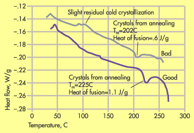
Figure 2. DSC comparison of good and bad annealed parts show additional crystals formed by annealing. |
Earlier in this series we covered a similar application where the difference in performance was found to be related to a change in the PTFE content. However, in this case the PTFE content did not vary, but a DSC scan of the part showed a substantial amount of amorphous structure. The processor decided that annealing would be preferable to a higher mold temperature, but the annealing conditions proved to be crucial to the part function. Figure 2 shows a DSC scan of two annealed parts, one that worked reasonably well and one that failed quite early. In the good part the characteristic recrystallization associated with cold molding has been removed while in the bad part a small vestige of this cold crystallization is still detectable.
But there is another measurable difference in the parts. It can be seen in the temperature region leading up to the main melting event. In both samples there is a preliminary melting event. This melting point is within a few degrees of the annealing temperature. The energy associated with this event is a relative indicator of the number of new crystals created during annealing.
The bad part shows a preliminary melting point of 202C (395F) and a heat of fusion of .6 J/g. The good part has a much higher melting point of 225C (437F) and also a higher heat of fusion of 1.1 J/g, showing that this part had been annealed at a higher temperature for a longer period of time. This test result allowed the processor to arrive at an appropriate annealing condition with a minimum of trial and error.
Relative vs. Absolute Crystallinity
One quick note needs to be mentioned regarding quantitative assessments of the degree of crystallinity. Some people want more than just a relative comparison of crystallinity; they want to see an absolute percent crystallinity. There is nothing wrong with this and we have made reference to such a calculation in earlier articles in this series. But the percent crystallinity is often misquoted, causing unnecessary panic while doing little to illuminate the root cause of a problem.
First, many high-performance materials only achieve a degree of crystallinity of 35 to 40 percent, even under ideal processing conditions. This number may sound bad, but it means that compared to a system where every polymer chain participates fully in crystal formation (something that never happens), a little more than a third of the structure becomes well organized. To make a valid calculation it is necessary to know the heat of fusion for one of these ideal structures. Then it is necessary to accurately calculate the area under the curve for the material in the part at issue. This process of integration used to be painstaking, but the computer takes care of it today.
Unfortunately, when computers start taking care of things, we humans tend to become disconnected from the significance of the numbers being generated. In order for this type of calculation to be valid, something about the material composition must be known. We received a frantic call from one client whose research group was performing degree of crystallinity studies on some PET polyester parts. They were coming up with values of 24 to 26 percent. They were told by the material supplier to expect 45 to 50 percent.
The calculations had ignored the fact that the material was reinforced with 50 percent glass fiber. The glass fiber does not participate in the melting transition, and it must be factored out. The same is true of mineral fillers, impact modifiers, and even other polymers that might be present in a blend. When the values were recalculated the actual degree of crystallinity was well within the desired range.
Postmold Shrinkage
It is possible to go on and on regarding the implications of crystallinity, but at some point we have to move on to other subjects. However, one last phenomenon bears reviewing. It is known as postmold shrinkage. The first time most of us encounter postmold shrinkage we are involved in molding close-tolerance parts. We establish a process, dutifully wait the hour or so that is required for the parts to reach room temperature, and measure some critical dimensions. We go home secure in the knowledge that we have debugged the tool.
A day or two later we are confronted by a quality assurance person who has performed the formal layout and finds several dimensions that are out of print. A comparison of the two sets of numbers shows that the parts have continued to shrink, usually by an additional .1 to .2 percent. In small parts this is often not noticeable. But as parts get larger or as tolerances become finer, these changes become an issue.
If we examine the history of these occurrences carefully, we find that they usually occur in the same resin systems—polypropylenes, polyethylenes, and acetals. All of these materials have two things in common. First, they are all highly semicrystalline; second, they all have glass transition temperatures that are at or below room temperature. We have already established that crystallization occurs below the melting point and above the Tg. Parts made in these three resins are always above their Tg, and the continued shrinkage is the direct result of continued crystallization.
How do we cope with this? The sound way to approach this is to minimize the delayed crystallization by maximizing the crystallization that forms during the molding process. In other words, use slower cooling rates provided by hotter molds. The manufacturers of acetals have been writing eloquently on this subject for about a quarter of a century. The hotter the mold, the better the properties and the long-term dimensional stability. This is particularly important if the part is going to see elevated temperatures during service.
Of course, this is not how we usually handle it. Instead we drop the mold temperature to reduce the shrinkage, and then if the parts come out oversized we reduce the pack time so that we put fewer molecules into the mold and lose gate seal in the bargain. Those molders who use scientific molding will see that this sets up the product for almost certain trouble down the road. The root causes of the problem lie in the chemistry and physics of crystallization. Process adjustments should never be made to compensate for the mechanics and chemistry of natural processes.
Hopefully, this tour of molecular structure has provided some useful insights into what are often baffling and expensive problems with long-term performance.
If you take only one thing away from this series, let it be this: Processors spend a lot of money on raw material every year. These materials are used because they have particular attributes. Many of these attributes arise from a crystalline structure. As long as you are paying for these properties, you might as well do your part to be sure they are actually developed during the molding process. The molder does have a role in property development. And the more exotic and expensive the materials become, the more critical that role is.
Contact information |
About the Author(s)
You May Also Like

