The Troubleshooter, Part 115: Even good living hinge materials have to follow the rules
Living hinge design rules are well known, but even a well-designed part will create problems if just a few elements of the melt flow path are not right.I had a surprise visitor last week, an old friend I had not seen or talked to for several years. Naturally, someone who visits in person is given priority over anything else I am working on at the time.
July 13, 2009
Living hinge design rules are well known, but even a well-designed part will create problems if just a few elements of the melt flow path are not right.
I had a surprise visitor last week, an old friend I had not seen or talked to for several years. Naturally, someone who visits in person is given priority over anything else I am working on at the time.
|
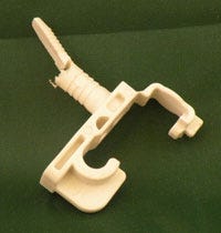
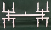
This friend’s name is Dave, and after catching up on the last few years, he handed me a runner system and a part that got our discussion started. Dave said this part with its three living hinges was giving him more fits than any part he had ever been asked to mold—the hinges were breaking most of the time, and there was warping, drooling, and stringing.
I measured the sprue, runners, and gates and could see his sprue and runners had dimensional issues, but at first glance the gates seemed to be OK. I checked the part again to see where it was gated and could not see anything obviously wrong with the location.
How to mold a living hinge
The key to good living hinge molding is to be sure the plastic flows across each hinge with a single material flow front. The flow path of the material from the point the material enters the cavity to where it reaches the end-of-fill point is often difficult to determine. I suggested that Dave sprinkle a little colored material in with the basic white he was using to see if he could get some color streaks to show up in the part and highlight the material’s flow pattern through the living hinge.
|
This flow check would help him figure out if the gate location was really in the right place or if he needed to find a new gate location that would generate better-functioning parts.
There are many living hinge designs. Most of them seem to work fine and some just barely work at all. If we need the hinge to flex only a few times, almost any design will work. If we need a million flexes, the design needs to be thought out carefully.
I remember seeing a living hinge design in Don Rosato’s Injection Molding Handbook some 25 years ago that has worked for me many times in my career. I also remember attending a John Klees seminar quite a few years ago in which he said that in order for living hinges to work well, it is necessary to run waterlines in the mold parallel with the living hinges. This was to keep the material in the hinge area in an amorphous state while the rest of the part would be crystalline. This would keep the hinge material from tearing easily.
I have used unfilled nylons, PBT polyesters, polyethylene, polypropylene, and many thermoplastic elastomers over the years in very successful living hinge applications. Filled materials make terrible living hinges.
I had Dave explain the number of flexes required of each living hinge incorporated into his part (less than 10) and the physical stresses the part would incur, including any chemicals or heats into which the part would come into contact. With this information, I suggested his problems were probably more in the nozzle orifice and the sprue.
Bad day at the orifice
I measured the nozzle orifice diameter at 0.125 inch, feeding into a sprue O-diameter of 0.135 inch. That appeared to be undersized for feeding plastic into these runners.
Where the sprue attached to the main runner it was 0.180 inch in diameter and 1 inch long. The sprue fed into a trapezoidal main runner that measured 0.190 inch deep, the connector link between the main and subrunners measured 0.160 inch deep, and the subrunner from the connector to the gate was 0.130 inch deep.
The runner dimensions were actually pretty good. It was just the sprue and nozzle relationship that appeared to be causing the warpage, drooling, and stringing problems Dave mentioned when he first handed me the runner system.
The sprue by itself measured OK for a nylon runner, but when used with a runner system with a 0.190-inch-deep main runner, we needed a sprue O-diameter that was 0.050 inch larger, or 0.240 inch. Since he was running unfilled nylon, that in turn required a reverse-taper nozzle with an orifice of 0.216 inch, or 0.025 inch smaller than the sprue O-diameter, on the outside and about 0.180 inch on the inside.
After going through all this investigation, we found out all we had to do was increase the sprue bushing diameter and inside orifice in a reverse-taper nozzle. I could tell the nylon was well molded due to the absence of bubbles or small foam cells on the part or on the small end of the sprue. I could also tell the nylon had not been degraded prior to molding since the natural color had not turned yellow in the dryer or when purged through the molding machine nozzle.
Nylon logic
It was time to discuss the usual twist when it comes to troubleshooting nylon applications. The toolmakers will argue that the sprue diameter needs to stay small to avoid slowing down the cycle. Somebody must have told them years ago that if the sprue is too big (thicker than the part), you end up running a slower cycle.
With few exceptions, the sprue is always thicker than the part. The barrel and nozzle heats, not a thick sprue, most often cause drooling and stringing. Once the sprue is opened up, the need for high heat settings is gone. The normal temperature for running a nylon 6/6 is 500°F in the barrel front zone, lower toward the rear, and the nozzle should be whatever it takes to stop drooling and stringing. Nylon 6 runs slightly lower heats—usually 15-25 deg F lower than the nylon 6/6. Just be careful that you do not let the nylon processing temperatures get below an actual melt temperature of 500°F and cause the nose cone to twist off the end of the barrel screw.
When confronted with drooling or stringing, molding technicians typically replace the nozzle or nozzle tip with a smaller diameter instead of simply reducing the heats. Why? Well, I would guess it’s because it takes 20 minutes to observe the results of a temperature change on the nozzle and it’s quicker to replace the nozzle instead of waiting for the heats to come down. I do understand this problem because the first 10 years of my life in plastics I did exactly the same thing.
Dave reviewed his notes with me to be sure we had covered everything, at which time he left for home. I told him to let me know how everything went once he made the changes and bid him good-bye.
His call came in a few days and he said it was easy to make the changes; the difficult part was convincing the toolmakers and molders that the changes would correct the problems. He did prevail and after a few adjustments to the front zone and nozzle temperatures, the parts started coming out fine.
Dave thanked me for the help, said the check was in the mail, and asked me if he could send more problem parts for me to review. I told him I would be glad to help.
Troubleshooter’s notebook
Part/material: Nylon part with living hinges
Tool: Eight-cavity cold runner
Symptoms/problem: Warping, drool, stringing
Solution: Enlarge sprue O-diameter from 0.135 inch to 0.240 inch; use reverse-taper nozzle.
About the Author(s)
You May Also Like


