By Design: False accusations
Jumping to conclusions often masks the actual problem.A large earth-moving machine crept slowly back and forth across the worksite. The driver performing this monotonous task was suddenly jolted into action by intense pain in his lower legs. The operator jumped from the moving machine and sustained additional injuries. Treatment of these injuries resulted in complications and the death of the machine operator.
April 7, 2010
Jumping to conclusions often masks the actual problem.
A large earth-moving machine crept slowly back and forth across the worksite. The driver performing this monotonous task was suddenly jolted into action by intense pain in his lower legs. The operator jumped from the moving machine and sustained additional injuries. Treatment of these injuries resulted in complications and the death of the machine operator.
|
The family filed a lawsuit naming the deceased’s employer and the original equipment manufacturer (OEM), who enjoined a custom molder. I was hired to help defend the molder who produced the allegedly defective part.
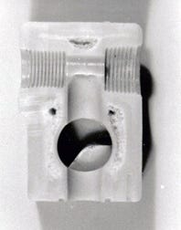
The source of the operator’s initial injuries was traced to a ride control valve located under the driver’s seat. A crack in the valve body had allowed hot hydraulic oil to spray onto the operator’s legs. The failed part (Figure 1) was an injection molded block measuring 1.500 by 1.625 in2 with a length of 2.375 inches.
During the discovery part of the litigation, it was revealed that the OEM designed the part to be machined metal. Preproduction machined samples performed as required, including passing a 2000-psi burst test.
The valve was quoted as both machined and molded. It then went into production as an injection molded glass-fiber-reinforced acetal part. There was no documentation indicating that the plastic valves were tested before being released for production.
Good material, bad design
It is unclear as to who chose the plastic material. There was no indication that a plastic material manufacturer was involved in the decision. It was, however, clear that the OEM approved that part design and plastic material. The part drawing and material specification was on the OEM’s drawing paper.
|
In retrospect, acetal was a good choice for the valve body. It has high tensile strength and the necessary resistance to creep, heat, and hydraulic oil. Acetal is, however, a crystalline, high-mold-shrinkage, notch-sensitive material with special design requirements.
The valve body may have been properly designed for machined metal, but it was not designed to the state-of-the-art for an acetal part. The cardinal rule for plastic part design is to maintain a uniform wall thickness. The thickness of the valve ranged from 0.300-0.800 inch. Thick walls stay hot longer and shrink more than thin walls, which produces stress at the junction of the thick and thin walls. Acetal is at its best with thickness variations of only 15%.
The maximum recommended wall thickness for acetal is 0.375 inch. The valve body was too thick for a good-quality acetal part. In Figure 1, the molded-in stress where the thick and thin walls meet and at the sharp thread cannot be seen. You can, however, see the three large voids. These voids are created when the plastic touching the surfaces of the mold cools quickly, stops shrinking, and becomes rigid. This happens while the center of the thick sections is still hot and shrinking.
At that point the rigid surfaces of the part can no longer be pulled inward as the center of the thick walls continue to shrink. This creates a negative internal pressure that pulls volatile gases, moisture, or unreacted monomer out of the melt to create the internal voids.
A faulty conclusion
The prosecution’s expert witness jumped to the conclusion that the valve body failed because of the internal voids. These voids were not on the part drawing and were, therefore, manufacturing deviations that rendered the valve body defective. If these accusations could be proven, the molder could have been found liable for producing a defective part.
The material supplier’s literature indicated that internal voids were to be expected on thick parts such as this valve body. These voids were due to the design of the part.
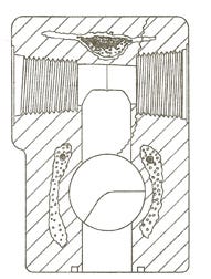
Careful examination of the failed part revealed that it had leaked through a crack, as shown in Figure 2. That crack was in no way associated with the internal voids in the part. The cause of that crack was traced to a sharp transition between the innermost thread and the valve body in a location near an abrupt change in wall thickness. The force that caused this sharp, stress-rising corner to crack was created by the male threaded fitting being driven too deeply into the inside thread on the valve body. That metal fitting actually left an indentation on the shoulder at the inner end of the inside thread.
The sharp stress-rising corner at the innermost thread was a design defect. The assembly operation that drove the metal thread too deeply into the inside thread was a manufacturing defect.
The custom molder’s defense team took the position that failure of the valve body was not the result of internal voids. The failure and the death of the machine operator was the direct result of a crack in the valve body caused by overtightening the threaded metal fitting and a highly stressed, sharp corner on the plastic thread. The OEM designed the valve and assembled the threaded metal fitting into the valve body. A favorable settlement was negotiated, but only after the molder spent a significant amount on his defense.
This case was settled before it went to trial, and the diverse opinions expressed by the opposing expert witnesses were never tested. It is, however, reasonably safe to assume that this incident could have been avoided by correcting the part design.
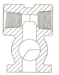
The high levels of molded-in stress could have been minimized and the internal voids could have been eliminated by redesigning the part to have uniform, thinner walls. Stress on the sharp innermost thread could have been reduced by radiusing the inner end of the inside thread (Figure 3). (Design guidelines for molded threads can be found in the October 2006, December 2006, and February 2007 IMM By Design articles.)
A shorter threaded metal fitting or a deeper inside thread on the valve body would have prevented the fitting from bottoming out. It is interesting to note that the redesigned part could be produced with a shorter molding cycle using less plastic material.
The two lessons to be learned from this story are:
1. The different plastic materials have their own unique design requirements. All plastic part designs must fulfill these specific requirements in order to be judged as designed to the state-of-the-art at that time.
2. The United States has 5% of the world’s population and 66% of the lawyers. Modern man is quick to litigate. Molders increase their liability whenever they mold parts that are not designed to the state-of-the-art. They may not be responsible for the defective design, but it can cost a lot of money to prove it.
About the Author(s)
You May Also Like

