The Troubleshooter: PART 102—Ejector pin gates have special needs
June 1, 2008
|
You won’t find a molded part on these pages this month; instead, we invite you to imbibe the words of wisdom from IMM’s 12-year Troubleshooter.
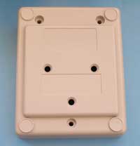
This month I was fortunate to receive a base for a control housing that was being molded out of a gray ABS material. The note in the box was asking for a complete review of the part as well as the runner system, including the sprue bushing.
When I am doing an in-plant review, I like to follow the material from the box or bag it arrives in, review the material dryer if they are using one, then check the barrel and screw, on through the check valve, nozzle, sprue bushing, runner, gates, and finally check the runner and part vents.
Sometimes I throw in a suggestion of what I think the cycle time should be and any other comments that might be appropriate for the molder or toolmaker to know about the part design or material choice they have made. However, this time I was not in their facility, so I would only be able to suggest what they should check on their end and do what I can on the rest.
Eliminate flow restrictions
The sprue dimensions were fairly typical, but the short runner connecting the sprue to the main runners was not deep enough to fully pressurize the main runners. The sprue O-diameter was 0.240 inch and it should have been 0.312 inch.
Once the sprue O-diameter was opened up to 0.312 inch, two changes could and definitely should be made. Once the changes are made, the molding machine nozzle orifice could be opened to 0.290-inch diameter from the existing extremely small diameter of 0.065 inch. The connector runner, since it was a modified trapezoid design, could be deepened from 0.245 inch to 0.3 inch. These changes would remove most of the restrictions from the flow path and help with opening the processing window to a less-restrictive size.
|
In addition, the molding machine nozzle should be changed to a full taper design, and the nozzle orifice should be opened up to the recommended 0.290-inch diameter. This would also eliminate restrictions to material flow.
What else needed to be done? I noticed the present gate diameter was only 0.065 inch feeding each curved tunnel gate, and these curved tunnel gates need to be 0.095 inch in diameter to feed a nominal wall thickness of 0.125 inch. The curved tunnel gate might have to be deepened, in a tapered fashion, but I wanted to sample the changes we already outlined first.
Final touches
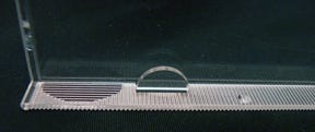
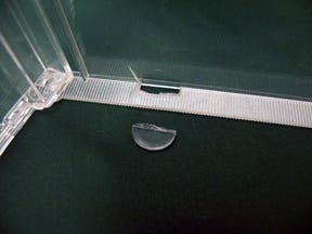
I also noticed the ejector pins being used to push the curved tunnel gates out of the runner plate were distorted. I would guess this was caused by the demolding temperature being a little bit higher than it should have been in an effort to speed up the cycle time. Or it could have been that the sides of the runner needed to be draw-polished to make the runner easier to eject when the mold opened.
Now for a guess at the cycle time. This was a two-plate, cold runner mold, running in a 300-ton molding machine. For these numbers, I like to use a multiplier of 250 multiplied by the 0.125-inch wall thickness for a cycle time of 31.25 seconds. Then I add 3 seconds based on 1 second per 100 tons of molding machine clamp tonnage for a target cycle time of 34.25 seconds. I usually round up, so the number I suggested to the molder was 35 seconds.
Did I miss anything? The molder asked me to review the part for mistakes or problems, which I just did. Overall, the part seems to be in pretty good shape. I see many inside sharp corners are not adequately radiused, but it would appear these sharp inside corners exist for a fit and function reason. They could always go back later and add at least a 0.015-inch radius to stop breakage problems in those areas.
The boss designs were right up-to-date and should function well for the ultimate customer. The pin gate, sidewall ribs, and other design components were designed right up to the latest suggestions being offered in the industry today.
Again, all the problem areas, other than some of the part radiusing, appeared to be in the machine nozzle, sprue bushing, runner and gate sizing, and runner and part venting. These were the problems I was introduced to in the 1960s, and amazingly, they still pop up here and there in 2008.
I called the molder and passed my suggestions on. He thanked me for my help, promised to send a check, and said he would let me know how things worked out for them. His answer came in a few days, and naturally, it was the one I wanted to hear. They are molding great parts and appreciated my help very much.
The Troubleshooter’s notebook Part/material: ABS control housing base. Tool: Two-plate cold runner mold. Symptoms/problem: Customer requested complete review of the part and runner system, including the sprue bushing. Solution: Relieve restriction to flow in the part by increasing the sprue O-diameter and maintaining the taper of the sprue bushing, machine nozzle orifice, and curved tunnel gate diameters. |
About the Author(s)
You May Also Like

