The Troubleshooter, Part 103: Make the right heating corrections
July 1, 2008
|
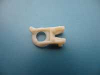
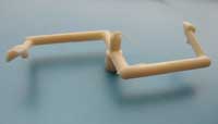
A new client sent me a small package with parts and a runner in it for review. The part looked pretty good to me but sometimes I don’t know all the functional problems and this looked like one of those times.
I flexed the part; measured the sprue, runner, gate, part wall thickness, and length of flow requirements; and ended up by checking the end-of-flow areas for dullness, a grainy area, or a black burn—the three stages of a burn associated with molding plastic parts—to see if the venting was doing its job.
Surprisingly, the part and runner checked out pretty close to standards that I like to use for crystalline materials. Small runners and gates and adequate venting are what I look for and these parts and runners seemed to fit the profile. So what was the problem?
A week or so later I got a call from a second-shift foreman who said he was the one who wanted some help with these parts. He had been reading my articles and thought it only natural that he should be asking me for help. After explaining that I now do this kind of work for a small fee, he called back with a purchase order number and asked me to explain everything to him over the phone and back it up with an e-mail. This seemed to be an acceptable arrangement to me so we began our discussion.
My review
First, I measured the sprue, runners, and gates. The 0.110-inch, cone-shaped sprue was fed by a heated sprue bushing with an orifice of about the same size. The transition area between the two sections contained melted material instead of showing the distinct features of the bushing and the sprue. No doubt it was a heat problem in one or both of these sections. I decided to save an answer on this part of the puzzle for later and asked my contact to e-mail me a copy of the process sheet for my review.
The part was designed well but had many sharp corners and edges on the core side of the mold that were not radiused. The gate location seemed to be in about the only place it could be without causing any other problems, such as part breakage or the ever-present overpacking of the gate area that also causes the part to crack at the gate. What bothered me most about the gate was not the location but why it had such a large diameter for such a small part wall thickness.
The person I spoke with had nothing to offer on why the gate feeding into a 0.045-inch wall thickness was also 0.045 inch. Normally the gate diameter is only 50% of the wall thickness into which it’s gated. We agreed this interesting clue probably meant the part did not easily fill, and making the gate bigger was the toolmaker’s way to get the parts to fill and pack.
|
Other measurements I took on the runner were 0.150 inch for the main runner and 0.145 inch for the section that ran from the main runner to the 0.120-inch subrunner that fed the gate. For crystalline material, the subrunner diameter that feeds the gate should be 1.5 times bigger than the wall thickness being gated into. With a 0.045-inch wall thickness, the subrunner needed to be roughly 0.068 inch. This meant that the subrunner diameter of 0.120 inch was plenty big enough to nicely fill and pack the parts.
The rest of the runner dimensions were sized progressively larger all the way back to the sprue bushing cone. The sprue cone O-diameter of only 0.110 inch that fed into the main runner diameter of 0.150 inch was the only pressure loss area I could see in the runner system. This pressure loss was what confused the molders and toolmakers into thinking that the gates needed to be larger. It was also what caused the distortion at the sprue cone O-diameter and the heated sprue bushing orifice; higher heats were used in this area in the failed attempt to make up for the restriction to flow caused by the 0.110-inch O-diameter. The correct sizing for the heated sprue orifice should have been 0.175 inch, not 0.110 inch.
The orifice of the sprue cone on the runner system would then be sized at 0.200 inch. Once this change was made, the heats in the heated sprue bushing could be reduced by approximately 50-75°F. Also, the cycle time could be shortened if the molder and customer desired it.
Adding heat the right way
I discussed this gate and heated sprue bushing orifice size issue with my contact and mentioned that there were many ways to get additional material into the cavity areas other than opening up the gate.
One option is to use higher material heats and increase the mold temperatures, or use higher injection pressures and speeds and even work on sprue and runner diameters to increase pressure at the gates. Even using higher backpressures and higher screw rpm will add heat.
Many changes can add or take away heat, but usually only one of these possible changes is the right one. The trick is to know which change will correct the problem and not cause the cycle to slow down or cause other defects in the part.
I also mentioned that adding heat to the process, either through the barrel heats or mold temperatures, can cause the cycle times to slow down in order to avoid distortion or warpage of the parts—both problems that should be avoided.
Although I found many problems associated with these parts, only the 0.110-inch dimensions of the sprue cone O-diameter and the heated sprue orifice dimension of approximately the same size seemed to be causing any problems.
I chatted for a few minutes with my contact and asked him to let me know if we solved his problem. A couple of days later I heard from him with good news: They were surprised that just a couple of hours in the toolroom made their problems disappear.
The Troubleshooter’s notebook Part/material: High-density polyethylene Tool: Two-cavity cold runner mold. Symptoms/problem: Customer requested complete review of the part and runner, which appears to have distortion problems. Solution: Increase the 0.110-inch sprue O-diameter and heated sprue orifice to 0.175 and 0.200 inch, respectively. |
About the Author(s)
You May Also Like
