The Troubleshooter, Part 107: Tiny TPU plugs
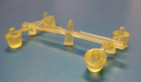
For trouble-free parts, follow these important rules when molding polyurethane. ?This month I received a small runner with four gates and a part—a plug—attached to each gate. The material was natural polyurethane (TPU) and the parts were as round as could be when using a single small edge gate on each part.
For trouble-free parts, follow these important rules when molding polyurethane.
?This month I received a small runner with four gates and a part—a plug—attached to each gate. The material was natural polyurethane (TPU) and the parts were as round as could be when using a single small edge gate on each part.
As often happens, there was no note in the box, but I’m getting used to these mysteries. Turns out it was from someone I go way back with and before long he called and filled me in on the problem as it appeared from his perspective.
|
Before the call, it had been a slow week so I decided to take a look at the parts. The natural TPU appeared to be well dried and was being molded in a four-cavity, two-plate mold fed by a heated sprue bushing. Alternately, this runner could have been one of many cold runners being fed by several hot drops in a hot runner mold.
TPU basics
Before we go any further, I refer all of you to one of my many points pertaining to molding. Rule #92 says that we mold big parts in big machines and small parts in small machines, but we do not mold many small parts in a big machine.
If these parts had been from anybody I had known for any length of time, then they were not running these small parts in a large mold; and this single important point almost guaranteed we were not dealing with a big hot runner mold trying to run 48 cavities or so of natural TPU. Don’t get me wrong—I have helped design and set up a 128-cavity, even a 256-cavity hot runner mold before, but it is hard to keep something like that running for very long. Parts stick in the mold, a slide quits moving, or any number of problems with the mold can shut us down in a hurry.
Instead of one hot runner mold with 128 cavities running in a 200- or 300-ton molding machine, I prefer to set up several 30- to 50-ton machines, each running a four- to eight-cavity cold runner, two-plate mold or even a small-cavitation hot runner.
Why? Mold maintenance. If I have a bad cavity in one of my four- or eight-cavity cold runner molds, when I shut it down for maintenance, I am only shutting down 10% or less of my productive output. When I have to shut down a big hot runner mold, my production is down 100%. When the big molds get shut down on the night shifts and don’t start up until the next day, production numbers suffer tremendously. I learned this lesson a long time ago and it is as true today as it was then.
Another problem here was just molding the natural TPU. First, it had to be dried extremely well in a desiccant-type hopper dryer at 180°F for soft-durometer TPU or 210°F for harder-durometer TPU. If you dry hard TPU at 180°F, it takes about twice as long to get it dry enough to mold well; and if you dry soft-durometer grades at 210°F, you see the pellets start to stick to each other in the dryer hopper. Bad news either way.
Also, the mold steel needed to remain unpolished in the sprue bushing, runner system, gate areas, and anywhere on the cavity or core steel. Why? Because TPU has a bad habit of sticking to any metal component that is shiny or glossy. It’s kind of like stretching a rubber band, where one end sticks to the mold steel. Some materials have newer lubrication packages incorporated into the TPU and they work a lot better than older grades, but they’re still not perfect.
I have a special method for molding TPU: Get the material good and dry, run the barrel heats in the low 300°F range for melt temperature, run both sides of the mold temperature at 50°F, make sure you don’t have any glossy spots, and inject it slowly.
Fixing the runner
Now that I have reviewed the basics of molding polyurethane, it’s time to share my observations on the parts and runner.
At first glance, the parts appeared to be fine. On closer examination I could see a small flow line on the top of one of the plugs that was still attached to the runner. This was fortunate since it was probably the only way I had to relate a part to an individual gate.
Under the magnifier, I saw more problems than were visible with the naked eye. There were small, airless voids in each part and even slight depressions into the side of several of these plugs. No doubt this was the reason for the rejected parts.
I saw several problems with the runner and gate that possibly were responsible for these defects.
• The feedpoint to the runner was too small. I measured the feedpoint cone O-diameter at about 0.090-0.100 inch. (It was hard to measure because the TPU compressed easily under the jaws of my dial calipers.) This meant the molding machine nozzle diameter could be sized to a maximum of 0.090 inch to feed this little runner. This was not the best situation, since we would no doubt have to apply higher-than-normal nozzle heats to the processing setup just to try and keep the nozzle from freezing off. I made a note to discuss with the moldmakers how much bigger we could open this feedpoint. We didn’t need much; even a 0.150-inch feedpoint O-diameter with a 0.135-inch-diameter nozzle orifice would be OK.
• The main runner had a depth reduction built into it right around the feedpoint to the runner. This depth reduction area reduced the main runner depth from the normal 0.120-inch depth to only 0.070 inch. This was a major restriction to flow and I needed to find out quickly why this design was used. I could not think of one good reason for this restriction and came up with about 100 reasons for not having it there.
The tiny subrunners seemed to be designed OK. They had a depth of approximately 0.070 inch as compared to the main runner depths of 0.120 inch.
• On the gate, the runners were full round, which is correct for an edge gate; however, the edge gate left the subrunner from its edge, not the middle as it should. Also, the 0.020-inch-deep gate was not deep enough for a 0.300-inch-diameter, 0.280-inch-thick part; it should have been around 0.050 inch. And finally, the gate land was about 0.090 inch and we all know a gate land should never exceed 0.030 inch.
What to do? When I heard from the molder, I explained my adjustments to the runner system so he could convey them to the moldmakers. The main issue was to eliminate the restriction in depth around the feedpoint to the runner. After the gate sizing was adjusted, I suggested he sample the mold to see if he also needed to go through my list of suggestions for molding TPU for any other possible changes. In a couple of weeks he will be calling back with his results and I am sure everything will work out just fine.
The Troubleshooter’s notebook
Part/material: Polyurethane plugs.
Tool: Probably four-cavity, two-plate mold with a heated sprue bushing.
Symptoms/problem: Flow lines, voids, depressions.
Solution: Enlarge feedpoint to the runner and nozzle orifice and remove restriction to flow in that location; gate from the middle, not edge, of the subrunner.
About the Author(s)
You May Also Like


