The Troubleshooter, Part 111: As good as it gets
A baffling problem with streaking requires not only in-depth detective work, but also a trip to Detroit.
March 19, 2009
A baffling problem with streaking requires not only in-depth detective work, but also a trip to Detroit.
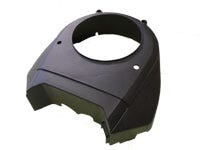
Around October last year I received a package from an automotive company just outside Detroit. I called the engineer who sent the parts and he said they had been having problems with white streaks on the surface for almost a year and a half. He then reviewed all the changes they had made to try and correct them.
After listening for a few minutes, I said I would look at the part and runner, measure a few critical dimensions, and come up with a list of changes for them to try.
|
The basics
I started my review by checking the part’s nominal wall thickness. It was 0.110 inch in some places and 0.125 inch in others. The ribs on the inside of the part also came in two thicknesses—0.110 and 0.080 inch. The material was a 15% glass-filled polypropylene.
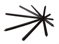
The spoke runner system had an off-center sprue bushing to allow the cold sprue to stay in the center of the mold and still maintain a decent flow of material to the gates located farthest from the sprue. The full-round runners that fed the edge gates were all 0.300 inch in diameter, and the gates were directly off the runners’ center—just like they should be. The sprue feeding the nine runners was undersized; it had a 0.200-inch O-diameter and was 0.260 inch where it attached to the runner.
So what did the runner dimensions need to be? Those that fed the gates needed to be 2.25 times the wall thickness, since we treat glass-filled crystalline materials the same as unfilled amorphous materials. With a nominal wall thickness of 0.110 inch, the runner diameters would all be 0.250 inch, so our 0.300-inch runners were fine.
With nine 0.300-inch-diameter runners, I could tell the sprue O-diameter was undersized just by looking at it. Did it need to be 0.312 inch instead of 0.200 inch? Let’s figure it out: With four runners coming off the sprue, we would increase it by 30%; with six runners, 35%; with eight, 40%; and with 10, 45%. Since we had nine, the calculation was to increase by 42.5% for a diameter of 0.428 inch.
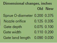
Now, that’s pretty huge for this application. The runners weren’t that long and PP with a light glass load would allow the material to flow fairly well, so I suggested they start out with a 0.375-inch sprue O-diameter and enlarge it if needed.
With the O-diameter at 0.375 inch, the general-purpose nozzle orifice needed to be 0.335 inch, or roughly 10% smaller (originally it was 0.125 inch). Normally a nozzle orifice this large might cause stringing or drooling, but if these guys watched their heats carefully, they wouldn’t have much of a problem.
Next, I looked at the gates to see if anything was out of kilter. They were 0.075 inch deep and 0.110 inch wide, and had a land length of 0.090 inch. Gates should be deeper with glass-filled material, and if the gates are deeper they must also be wider. The land length requirement always remains the same.
|
Let me put some numbers to these rules for glass-filled materials. The gate depth should be 75-90% of the wall. I used 90% for this calculation given the size of the part. The wall thickness of 0.110 inch multiplied by 90% gave me a gate depth of 0.100 inch.
The width of an edge gate for a part this big is two times the gate depth, or 0.200 inch instead of 0.110 inch. The gate land needed to be one-half the depth but not exceed 0.030 inch. This meant the edge gate land length needed to be 0.030 inch for this part.
I got the molder and toolroom supervisor on the phone and told them the changes they needed to make. Then I told them that as long as they were making changes to the mold, we might as well get rid of the quick-disconnect waterline couplers and waterline loops. They said they would work on the changes and let me know how it turned out.
In-person assistance
I got a call a week later and they were not very happy. They said all the changes had been made, the mold sampled, and the parts looked a little better, but they were still getting a lot of rejects due to surface streaks. We tried to discuss the surface-streaking problem over the phone but didn’t have much success figuring out the problem. We finally agreed it would be best if I made a trip to Detroit to see for myself what was causing their 20%-plus reject rate.
When I arrived, I checked the mold for all the changes I suggested, even the quick disconnects and hose loops. To my surprise, they all had been made. The molder had even added vacuum venting to be sure nothing was left to chance.
We started the molding machine, waited for the mold temperatures to stabilize, and began checking surface cosmetics. We still had streaks in a few places. The reject rate was lower but not by much—between 10% and 15%.
Did we miss something? I asked Bill, the lead molding technician, to give me a list of process changes they had tried before they made my latest round of changes, and then asked him to run the original process conditions. He changed the heats, speeds, pressures, mold temperatures, and cycle times. When we were finished, Bill looked at me and asked, What next?
I asked him what the high and low settings were for the heat, speeds, pressures, mold temperatures, and cycle times, mostly to see what was helping or hurting the part surface appearance.
He told me he had run the barrel heats down to 400°F and up to 550°F but had not seen much of a change. The injection pressure was rising and falling as the barrel heats went up and down—no big changes to surface defects. The pack and hold pressures didn’t help. Bill said the screw rpm was slow due to the glass bundles in the material, and same with the backpressure; I told him low and slow was best for glass-filled materials.
When he told me the mold temperatures had been run down to 50°F and as high as 125°F, still with no change to the surface look, I stopped him. I told him that 125°F was just a medium temperature for glass-filled PP and he should go higher. He raised the heats to 175°F on both sides of the mold and we started molding parts again. Lo and behold, the first part out of the machine was a keeper. So was the second one. We did not get a reject up through part number 20.
The perfect storm
Here was the question: Why did a hotter mold work on the mold trial and not before? Before my changes, they were getting restrictions to flow, the material heats were not uniform throughout the mold, and parts were warping so badly they couldn’t tell if a hotter mold was helping.
After my suggestions were implemented, the material heats could be lowered in the barrel and nozzle areas, and once the restrictions to flow were removed, the material could be molded more easily and react to the changes we had made in the mold to improve the flow of material.
The week after I returned home, I got a call from the department head in charge of engineering. He wanted to extend his gratitude to me for solving a problem that had baffled them for almost two years. I thanked him for his kind words, and then got back to working on a project that had just arrived from another molder.
The Troubleshooter’s notebook
Part/material: 15% glass-filled PP automotive part.
Tool: Single-cavity cold runner.
Symptoms/problem: Surface streaking.
Solution: Modify gate dimensions; enlarge the nozzle and sprue O-diameter; remove quick-disconnect water couplers and
waterline loops; raise mold temperature.
About the Author(s)
You May Also Like

