The Troubleshooter, Part 112: Finishing touches
Some parts and runners are easier to fix than others.It was one of those really cold winter days here in the Midwest. The sky was snowing and the wind was blowing when, a little after 8 a.m., the FedEx driver showed up at the door with a package of parts and runners sent by my good friend from many years of doing work together.
April 3, 2009
Some parts and runners are easier to fix than others.
It was one of those really cold winter days here in the Midwest. The sky was snowing and the wind was blowing when, a little after 8 a.m., the FedEx driver showed up at the door with a package of parts and runners sent by my good friend from many years of doing work together.
|
I opened the plastic bag with the parts in it, reviewed the print, and read his note. He wanted help getting rid of occasional short shots and sometimes he was getting a rough surface finish on the part, mostly in the gate area or straight out from the gate.
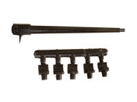
When I first looked at the package contents, it appeared that the unbalanced runner was detached from the cold sprue and only one side of the runner was included. I could tell what the full shot looked like just by looking at the sprue and the one side of the runner that he did send. I could also see right away that the sprue diameter was on the small side, but it didn’t seem to be so small as to cause the problems indicated in the note.
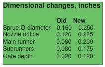
Then I looked at the main runner, and that was where I noticed that it was a shallow half runner coming off only one side of the sprue—not both sides. It was 4 inches long, the subrunners were only 0.250 inch long, and the sprue was 3.250 inches long. The one problem I could see so far was that the main and subrunners were both very shallow half-round runners. The depth of the main and subrunners were all uniform at 0.080 inch, which, as you might guess, is too shallow for the ABS used in these parts.
The sprue O-diameter was only 0.160 inch and the nozzle orifice diameter was 0.120 inch. Plus, the latter was a general-purpose nozzle, which is not appropriate for ABS; it should have been a full taper.
|
I typically design a sprue and runner for ABS parts with much larger diameters, such as 0.250 inch for the main runners and 0.225 inch for the subrunners. They did not need to be quite that big for this part since the sprue and runners were pretty short and the parts were fairly small. So I determined that the main runner needed to be 0.200 inch and the subrunners 0.175 inch, and both changed to full-round runners.
With the main runner at 0.200 inch, the sprue O-diameter would be 0.250 inch and the full-taper nozzle feeding into the sprue would have a 0.225-inch diameter.
Next, I measured the gates and found they were only 0.020 inch deep and 0.130 inch wide with a land of 0.030 inch (at least they got the land right). The thickest wall section of the part was 0.160 inch, so the new gate depth would be 0.120 inch since the material is ABS. With a 0.120-inch gate depth and the parts so small, we could get away with leaving the gate width at 0.130 inch.
Venting and wrapup
This review seemed to be pretty easy; about all that was left to do was go over the part and runner venting. I looked at the end-of-fill areas on the parts, at the sprue puller, and at the end of the runner for dullness, a grainy look, or flat-out black burns. With black parts, I periodically run them out of natural or light-colored material to check for burns. Or, sometimes I can see burns on black material by using 5x or 10x magnification.
I did not see any burns using magnification, so I noted that the end of the runner should have vents that were 0.003 inch deep. This depth would then be extended 0.060 inch from the runner parting line, followed by a drop into a 0.040-inch-deep channel to atmosphere. The width of the vent would be the same as the vented runner diameter, and the vent lip then draw-polished to a mirror finish to make the vent self cleaning.
The sprue puller is another good place to air, but it’s vented by taking 0.0015 inch off the end of the core pin being used for the sprue puller. In this case, drop down 0.060 inch and cut a flat on the side of the sprue puller to move the vented air to the head of the pin. From that point the air should naturally vent to atmosphere. Finally, draw polish the end of the sprue puller to make it self-cleaning.
I called the molder, passed the information on, and waited a few days to get the results. When the call came in, the news was good and I received my check in the mail. All in a day’s work.
The Troubleshooter’s notebook
Part/material: Black ABS.
Tool: Multicavity cold runner.
Symptoms/problem: Short shots, rough surface finish.
Solution: Increase sprue O-diameter and nozzle orifice; change from a GP to a full-taper nozzle; increase diameter of main runner and subrunners; change all half-round runners to full round.
About the Author(s)
You May Also Like


