The Troubleshooter, Part 116: Keep the toolroom informed
Proper gate and runner design starts with the moldmakers, so make sure they know the material specs.It was one of those great Midwest rainy days when the FedEx driver rang the doorbell. The box I signed for was a small one as boxes go, and the return address brought a smile to my face. The note inside the box confirmed it was indeed from a former inside tech guy that used to work for one of the big material manufacturers from an era now gone by.
July 30, 2009
Proper gate and runner design starts with the moldmakers, so make sure they know the material specs.
It was one of those great Midwest rainy days when the FedEx driver rang the doorbell. The box I signed for was a small one as boxes go, and the return address brought a smile to my face. The note inside the box confirmed it was indeed from a former inside tech guy that used to work for one of the big material manufacturers from an era now gone by.
|
According to the note, my old friend was now working part time for a big molder in Florida. He said that the part in the box was molded out of an olefin material and all of his previous experience was with amorphous materials. He just wanted me to provide him with a second opinion.
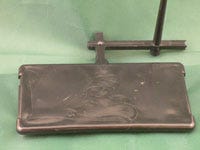
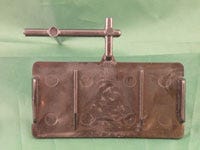
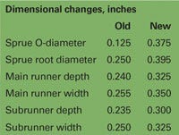
I looked at the part and could easily see flow lines and wrinkles on its surface, originating at the gate and flowing straight out from it. The sprue was 3.5 inches long with an O-diameter of 0.125 inch and a root diameter of 0.250 inch, and attached to a trapezoidal main runner that was 0.240 inch deep and 0.255 inch wide. The subrunner was also trapezoidal and measured 0.235 deep by 0.250 inch wide.
The gate looked like an afterthought. First, it came off the side of the subrunner, which is a profile I use in my seminars to indicate a problem with using trapezoidal runners with edge gates. Second, it was very thin—only 0.060 inch thick for a part with a nominal wall thickness of 0.200 inch. And third, the land length of this fan gate measured 0.190 inch instead of the traditional 0.030-inch maximum.
Expanded materials data
The material was identified as high-density polyethylene but I had no information about melt flow or molecular weight. Now, when working on any part and runner, I always look up the material on the IDES Prospector database at www.ides.com. (Hey, why not? I use the free part.) The Prospector database can give you a complete profile of almost any material being sold these days. I looked up the material and found out it was just a standard HDPE with a melt flow of only 5, which is pretty low.
This material information is what you need to tell the toolroom folks so they know how to design the gates and runners. Sometimes the tooling engineers or material suppliers help the toolmakers out in this area, but most of the time they don’t know the needs of the different materials themselves.
The problem with knowing the melt flow of a material is that you also need to know the condition under which the melt flow test was administered. The condition number such as G, H, I, or whatever the condition calls for tells us at what temperature the test was run and what weight was applied to give us the melt flow number. Lately I have noticed more and more data sheets are indicating a “flow condition” alpha character close to the melt flow number.
|
I have never thought the melt flow test accurately represented the actual flow properties of a given material because the melt flow test does not take into account the shear-thinning properties that injection speed provides us in actual production conditions. A spiral flow test is a much better indicator of the real flow properties for a given material than the melt flow test. (Newer tests to determine alternate flow properties were on display at NPE2009.) The spiral flow test numbers are now being supplied to us by a few of the material companies.
The spiral flow test requires a special mold that is clamped into a molding machine and each material being tested will be run according to specific heats, speeds, pressures, and mold temperatures given to us by the material companies. Then the material is injected into the mold and we see how far the material flows in the circular pattern cut into the mold. This circular pattern is cut in 1-inch increments, so if the material you are testing flows 28 inches with the parameters given, then you have a spiral flow number (SFN) rating of 28. (Molders can buy a spiral flow mold and do the testing themselves if they want or the material manufacturers can buy a mold and test their materials for us. I suspect it will be the material manufacturers that end up doing the testing and providing us with the spiral flow numbers for each of the materials they sell.)
Logic must prevail
Continuing with my visual review, I could see foggy areas on the part surface between each of the ribs. These areas most likely indicated an underpacked condition or a venting problem in the mold. Of course, they could also be the result of somebody running the barrel heats higher than normal in an effort to get the material to flow through a restricted gate and undersized nozzle orifice.
The rest of the part looked to be OK, even the 0.100-inch rib thickness in relation to the 0.200-inch nominal wall. The rule for polyethylene is that the rib thickness should be no more than 50% of the nominal wall thickness. All high-shrinkage materials need to abide by this rule.
At this point, I felt certain that the major problems with this part were the small sprue O-diameter, the resulting small nozzle orifice, the long gate land length, and the shallow gate. I also saw other areas that would have been good to fix, but I preferred to discuss each of these other areas with the molder individually to see why the rules were broken in the first place.
For instance, why was the gate design so restricted? Was it to make it easy for an operator to break the gate free from the part without having to use a degater? It begs the rhetorical question: Which is better—a good-looking part, or a part that snaps away easily from the gate?
I started on my list of suggestions to pass on to the molder:
1. With a trapezoidal runner design, I start with the depth of the subrunner that feeds the gate. In this case, the nominal wall thickness was 0.200 inch; this means the subrunner needed to be 1.5 times the part thickness, or 0.300 inch deep (it was only 0.235 inch). The width also needed to be increased to 0.325 inch from 0.250 inch.
2. With a 0.300-inch-deep subrunner, the main runner needed to be 0.325 inch deep instead of 0.240 inch, with a width of 0.350 inch instead of 0.255 inch.
3. The sprue O-diameter needed to be opened up from 0.125 inch with a root of 0.250 inch to an O-diameter of 0.375 inch and a root of 0.395 inch.
4. The general-purpose nozzle orifice diameter needed to be 0.344 inch to properly fit into the 0.375-inch sprue O-diameter. I picked 0.344 inch because it is an 11⁄32 fractional size and is the largest off-the-shelf nozzle that’s close to our requirements.
5. Venting is something I can’t see from looking at a part and runner. I could visualize that the sprue puller, runner, and parting lines are properly vented but I couldn’t be sure without seeing the mold.
6. I also couldn’t tell where the waterlines were located so just to be safe, I recommended that they not be looped on the back side of the mold. Quick disconnects should be eliminated or be upgraded to the next larger size.
7. My cycle time estimate for this part was approximately 250 times the 0.200-inch nominal wall thickness, or 50 seconds. Because of the higher-than-normal barrel heats and unknown water cooling, the present cycle was probably at least 75 seconds. If they opened the flow path and corrected water problems, they would no doubt get the cycle time down to at least 50 seconds and probably get the final cycle time into the 35- to 40-second range.
I e-mailed the molder with my suggestions and received a call from him within the hour. He had already given the toolroom my suggestions and they were going to have the mold back into production in a couple of hours. The molder said he was very relieved to get these problems fixed so he could finally start molding parts he could ship. I was just glad to have been asked to be part of the solution.
Troubleshooter’s notebook
Part/material: HDPE.
Tool: Single-cavity cold runner.
Symptoms/problem: Flow lines, wrinkles, foggy areas emitting from the gate.
Solution: Increase subrunner, main runner, sprue, and nozzle orifice dimensions.
About the Author(s)
You May Also Like

