The Troubleshooter, Part 117: The 10% loss—slow cycle times
Getting the last bit of profit out of your process often depends on a properly designed tool.
October 21, 2009
Getting the last bit of profit out of your process often depends on a properly designed tool.
The FedEx driver walked into my office yesterday with a small package that promised to reveal a problem of some kind. I signed for it and proceeded to the breakroom for a cup of coffee.
While sipping I decided to get out my pocket knife, the one I won as a Poor Boy Award some 40 years ago when I used to show my Classic Taylor Craft BC-12D tail dragger airplane. The Poor Boy Award was presented by a delegation from South Carolina at the Experimental Aircraft Assn. in Osh Kosh, WI and has been one of my prized possessions all these years. It is also a good letter and box opener so I applied it to the box I just received from FedEx. A rectangular part with runner attached fell into my hand. No note, as usual, but I can generally figure out what the problem is without one.
|
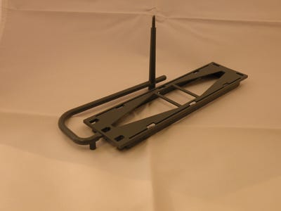
This part looked like the faceplate on an in-dash stereo system, but probably was not. The material was PC/ABS or possibly just ABS, based on the stiffness of the part and the look of the material vestige at the sprue O-diameter. The part was not bowed in any way and I didn’t see any sink.
It almost looked like this would be considered a “good” part. I looked in the box again to see if any “bad” parts were available. Nope, not a one. At that point I must have looked confused since my son walked into the breakroom for something to drink and asked me if everything was all right. He sat down and asked to see the part.
He looked it over and suggested the problem was probably the knitlines on the two strips of material holding the two sides of the part together or at least maintaining the dimensions of the part width. I had to admit I did not see the white mark right in the middle of each of the two connector strips. I told him I thought it was the slight amount of surface splay that was on the part just inside the edge gate at the end of the part.
We bantered back and forth for a few more minutes and he headed back to the shipping area to get back to sending out books. I decided I needed a place to work where I could use a brighter light and have something to magnify the defects. So it was back to my desk to finish my review.
I like to start with the part dimensions, move on to the runner that feeds the gate, check out the sprue bushing, look at the end of the sprue to guess the nozzle orifice size, and then back to the gate.
The part was 0.050 inch thick all over. Nothing was breaking off in the mold, and it looked pretty good to me. I did see six snapfit components, three on each side of the part, all facing the middle, but they appeared to be functioning normally.
I think we found the only two problems on this part: the knitline in the middle of each of the two inside straps and the little bit of splay about an inch or so inside the gate on the surface.
|
Attending to the details
The knitlines on the two straps were being caused by the material flow splitting as it entered the cavity and going down both sides of the pyramid-shaped core, then entering the two straps from both sides, trapping air at the middle of both connector pieces. Any time you trap air in areas like this you will see a knitline where the air is trapped. If you push on this knitline the connector piece will snap there.
To get rid of this knitline, we needed to place a relief area on one side of the air entrapment into which trapped air could vent. These needed to be self-cleaning vents designed like parting line vents. For a material like this, the depth needed to be 0.001 inch and the width 0.200 inch, with a 0.040-inch vent from the parting line dropped into a 0.040-inch-deep channel to the relief area we just installed. The last piece of the puzzle was to be sure these vents were all draw polished to an A1 or mirror finish (this makes them self cleaning).
Now to tackle the barely noticeable surface splay just inside the gate. The rule for this is, if blush is at the gate, the gate is not deep enough. If splay is just beyond the gate, the land is too long. If the splay is about halfway between the gate and the end-of-fill area, it is usually shear splay. I measured the gate land and got a reading of 0.115 inch, which made me think the problem was that it was too long (the gate land should never be more than 0.030 inch long, no matter what material is being used). Besides, shear splay looks a little bit rougher than moisture or heat splay.
The gate was 0.075 inch deep and 0.150 inch wide. The critical part of this gate review is that the gate was coming off the edge of the main runner. An edge gate should always come off the center of the runner feeding the gate, never the side. When the edge gate comes off the edge of the runner, you effectively turn it into a high-shear gate, and surface splay just past the gate is always the result. This means we had two reasons for surface splay just inside the gate—the land was too long and the gate was not designed to come off the center of the feed runner.
The full-round main runner was perfect for an edge gate and its 0.240-inch diameter was classic sizing for an amorphous material such as we had here. The sprue was 0.215 inch at the O-diameter and 0.290 inch where it attached to the main runner—undersized for running a thin, flat part such as this one. Better sizing would be 0.312 inch for the O-diameter and 0.375 inch where it attached to the main runner.
The last area to be reviewed was the orifice size of the nozzle. By looking at the narrow end of the sprue, I could measure the nozzle orifice diameter at 0.135 inch. The rule is that the nozzle orifice should be 90% of the sprue O-diameter, so once the sprue changed to 0.312 inch, we would want the nozzle orifice to be 0.290 inch.
I guessed the undersized dimensions and restricted gate area were causing the molding technicians to raise their barrel heats and slow down their injection speeds, all of which contribute to slow cycle times and cosmetic defects.
Calculating cycle time
What should the cycle time be on a part like this? When I multiply the 0.050 inch wall thickness by 250 I get a 12.5-second cycle, and if I add a couple more seconds for a 100-ton machine I get a 14.5-second cycle time. I would round it off to 15 seconds as a target cycle. Now, most custom molders probably do not have a 100-ton molding machine sitting around waiting for a job to show up, so they will run a part like this in their 250-ton machine, and that will add 3-4 seconds to the cycle due to slower platen movements and so on, bringing the cycle time up to 18 or 19 seconds.
This is how the average molder comes to be running cycle times around 25% longer than they should be. This little error will cost a molder about 10% of its profits. Instead of making the 16.7% profit margin most of us quote, we end up with 5%, maybe 6% at the end of the year.
The molder called a little bit later in the day and asked if I had received his package. I told him I had and asked if he wanted to talk about the air trapped in the knitlines on the two strap connectors or the surface splay near the gate. He was quiet for a moment, and then said he was more interested in the slow cycle times he was getting. I told him to get pen and paper and I would go through it with him.
I think I will go out on the patio and enjoy an iced tea to celebrate another job coming together as nicely as this one did.
Troubleshooter’s 
notebook
Part/material: PC/ABS or ABS faceplate.
Tool: Single-cavity cold runner.
Symptoms/problem: Knitlines, surface splay just inside the gate, slow cycle time.
Solution: Vent near air entrapment area; move gate from the edge of the main runner to the center; decrease gate land length and increase sprue diameters (both ends) and nozzle orifice.
About the Author(s)
You May Also Like


