The Troubleshooter, Part 118: Be careful where you gate
A thin-walled part misses some basic design rules, and suffers for it.
December 7, 2009
A thin-walled part misses some basic design rules, and suffers for it.
I thought that in September, starting the month with a holiday might slow down the parts being sent to me for review. Thankfully, this didn’t happen. Sure, we are in a slowdown, but many of my regular customers seem to be doing OK. Some are not faring as well as others, yet are surprisingly busy in spite of the economy and a reduction in their automotive work.
|
Anyway, almost on cue, the UPS driver pulled up and delivered a small box full of parts and a runner for me to review. Fortunately, this time I had a full set of paperwork that gave me the problem, who sent the part, my contact, and the proper person to send the bill. This might be starting off as my best review yet, at least for documentation.
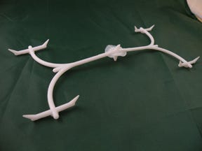
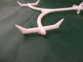
You could tell this was a fairly new mold because of the curved subrunners going out from the main runner to the second-level subs that were feeding the subgates. Only a CNC machine makes runners curvy and pretty like this. The old molds made with mills of the day were all squared off with those 90° angle runners. It really does not matter—they both work fine.
I looked the runner system over and saw the nylon 6 indicated on the setup sheet was indeed the natural material I saw in the runner system and the parts. As one of the more lubricious materials in the marketplace, nylon was a good choice for this application. I could also see we were working with an eight-cavity mold producing a part about the size of a fifty-cent piece, but with thin walls.
|
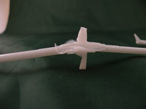
The feedpoint in the center of the main runner was fed by a heated sprue bushing, and the toolbuilder had left the sprue bushing to float a little bit so we would end up with a thin disc of plastic to help hold the main runner together when the mold opened up and ejected the eight parts. Maybe it was done on purpose, maybe not. I like to think all the components of the runner are there for a reason.
The subrunners that fed the gates were full round, which is always a good idea, and their diameters were 0.150 inch. The curved subrunners that ran from the main runner to the subrunners just off the gate were full round with a diameter of 0.145 inch. Something was not right here. These runners should not have all been the same diameter, as there would be some pretty hefty pressure losses.
The main runner feeding the curved subrunners was full round, with a diameter of 0.150 inch. The plot thickens. The thicker disc around the runner feedpoint was 0.175 inch thick and the thin disc that was probably just a mismatch was only 0.020 inch thick.
The cone-shaped feedpoint to the runner looked to be 0.150 inch in diameter and the heated sprue bushing feeding the feedpoint was about the same. Sometimes it is hard to tell for sure what the actual dimensions are on runners like these, and any setup sheets I end up with seldom include this kind of information. Being in the toolroom with the mold opened up is the only sure way to get these dimensions.
A graduated approach
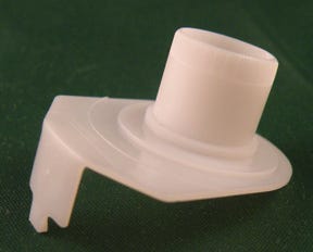
The parts themselves had fairly thin walls—approximately 0.030 inch everywhere I could measure. The part looked like a bushing of some kind that no doubt held a shaft. The bearing portion was attached to a flat support piece and the support piece had a small flange attached to it on one side—probably just a place to gate into. This would not be my first choice for a gate location.
The gate was in the middle of the small flange wall and measured about 0.025 inch—not unusual for small, thin-wall parts. The only problem here might have been trying to gate on a flange that was 90° to the support wall, which was 90° to the bushing section. Additionally, there were 90° angles with no radius where the flange attached to the support bracket and where the support bracket attached to the bearing section.
Nylon is a fairly notch-sensitive material, so it is important to radius all the sharp corners or edges. Yes, it should say so on the print, but many times the radius information is accidentally left out and if the toolmakers do not take the initiative on their own, it does not get done. I think this might have been the situation here.
I checked the paperwork to see exactly what this customer wanted me to look at but all it said was that parts out of each of the eight cavities were not dimensionally the same as all the other cavities, and not the same as in one of their older molds.
No doubt the problems I had uncovered in my review would explain in large part the inconsistencies. It all comes down to different toolmakers working on each of their molds.
I should probably tell them that when I was in Japan several years ago, I noticed the molding shops preferred to run mostly small-cavitation molds, usually four-cavity or less, not high cavitation (96 and above). I think if the Japanese toolmakers I was working with had their way, all their molds would have four cavities or less so they could be sure that all parts would have reproducible dimensions.
It all seemed pretty straightforward to me now. This molder needed to sit down with the appropriate toolmakers and correct the sizing problem of the runners. Right now the runners were all about the same 0.150 inch diameter instead of stepping up the dimensions from the subrunners that fed each gate, through the curved subrunners, into the main runner, and finally the feedpoint cone in the center of the main runner was the largest section in the runner system, with the heated sprue orifice just a little smaller than the feedpoint cone dimension.
The subrunners feeding the gates could be 0.150 inch in diameter, the curved subrunners could be 0.175 inch in diameter, and the main runner could be 0.200 inch in diameter, with a 0.250-inch-diameter feedpoint to the runner and a 0.225-inch-diameter heated sprue bushing orifice. It is just this simple to straighten out a wayward runner and get the pressure drops back where they belong.
To-do list: fix gate, radius, polish
But how about the parts themselves? Gating the part closer to its geometric center would have been better than gating on the flange. I guess the gate could be left on the flange, but it would take a lot of trial and error and resizing of the flange thickness to better transfer nylon through the flange into the support wall and the bearing walls. In my opinion, the gate location was critical to the success and repeatability of these parts.
Moving the gate away from the flange and up to the support wall would make all of these part dimensions pretty much OK. But even then, the toolmaker might have to slightly thicken the flange wall to allow the nylon to flow more uniformly into the bearing walls, as well as back down the other direction into the flange.
We needed to address the lack of proper radiuses at the intersection of the flange and support walls, as well as where the flange met up with the bearing wall. These were all inside corner radius requirements, where two walls of equal thickness met, and as such, the proper radius for where each of these walls came together would be equal to 50% of the walls being attached to. The 0.030-inch-thick walls meant we needed to use 0.015-inch radiuses where all these design components joined with each other.
Another point to remember was that the higher we polished the surface of the steel, the smoother and glossier the surface of the nylon would be and the slicker the surface of the bearing section, so the better and longer the part would perform. At least, this would be true if the shaft running against the bearing wall was not roughed up in any way.
This was about all I could do for these guys the first time around. I called the molder and gave him the laundry list. After about a month I heard back. He said they made every change I suggested, sampled the mold, and found out the dimensions were spot-on, so they left the mold in the machine and started running production. Another job running amazingly well; this is as good as it gets.
Troubleshooter’s notebook
Part/material: Nylon bushing
Tool: Eight-cavity cold runner with heated sprue bushing
Symptoms/problem: Part dimensions from both the same and different molds were inconsistent.
Solution: Use graduated sizing for the runner system; gate the part closer to its center, not on the flange; thicken flange wall; radius all sharp intersections; highly polish mold steel.
Dimensional changes, inches
Old New
Curved subrunners 0.145 0.175
Main runner 0.150 0.200
Feedpoint to the runner 0.150 0.250
Heated sprue brushing 0.150 0.225
About the Author(s)
You May Also Like

