The Troubleshooter, Part 119: No sharp corners
A large part contains a multitude of radiusing sins.The big brown truck pulled up downstairs, and the driver jumped out the door, actually running to my office. (Where do they get these guys and gals?)Today the driver was a no-nonsense young lady who was short on small talk but quick on getting the package to me. I signed my name; the lady left and I got out my South Carolina pocketknife and opened the package.
December 22, 2009
A large part contains a multitude of radiusing sins.
The big brown truck pulled up downstairs, and the driver jumped out the door, actually running to my office. (Where do they get these guys and gals?)
Today the driver was a no-nonsense young lady who was short on small talk but quick on getting the package to me. I signed my name; the lady left and I got out my South Carolina pocketknife and opened the package.
|
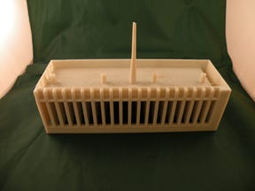
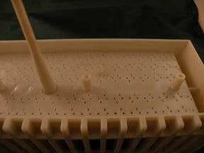
Inside was a single molded part with a sprue attached. There was no note, but somehow I’m getting used to that. The material appeared to be polycarbonate or at least an alloy of PC and something else. I could tell it was an amorphous material, with the shrinkage in the 0.005- to 0.007-in/in range (0.005 in/in in the direction of flow and 0.007 in/in in transverse or cross-flow sections—not the 0.006 in/in shrinkage that a lot of toolmakers like to assume). It would also be fairly rigid and would not be very chemically resistant.
Polycarbonate is a great material. It gives us good rigidity and low shrinkage (less warpage), comes in flame-retardant and high-molecular-weight silicone oil grades, and has great impact values if we do not forget to put radiuses in where they belong. Also, it has very good clarity and produces a high gloss if needed, but it just isn’t very chemically resistant. The price of the material has always been on the high side but we get a darn good material that works in many applications for a price we can usually live with.
Failure to radius
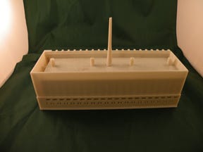
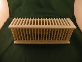
But I digress. On one of the part’s long sides I could see 20 vertical slots that were about 0.250 inch wide and a little more than 1.5 inches long. The other side of the part did not have any large slots but it did have small rectangular slots that were very narrow, not very long, and both vertical and horizontal.
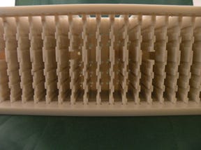
On the inside were full-width ribs that were about 0.150 inch thick, spaced 0.250 inch from each other, and I counted 20 ribs altogether. I only mention all this detail because I could not see anywhere that these slots had a single radius. Why is this important? For one thing, these sharp corners would drastically reduce the impact rating of this part.
Polycarbonate is a terrible material when it comes to notch-sensitivity issues. All sharp corners and sharp edges must have a radius applied to them or the Izod impact values in these sharp areas will be reduced by as much as 90%. Why buy PC for the high impact ratings when the sharp corners are going to reduce the available impact levels to about the same as high-impact polystyrene?
I looked the part over very thoroughly and could see hundreds of sharp corners throughout this otherwise well-designed part. I couldn’t find a single radius on any of the ribs where they were attached to a sidewall. Inside corners like these should have a radius equal to 50% of the nominal walls. The sidewalls and rib thickness were about the same at 0.150 inch each, so the radius should have been 0.075 inch.
Even the small slots on the bottom level of this part had 90° sharp corners—ideal places for cracks to appear. This was also the wall where the sprue was connected, and I could see that many of these little slots located near the sprue were being flashed shut by the injection pressure, excess material heat, waterlines not located in the proper areas, or something else I had not noticed yet.
|
Too much taper
The only thing left in my review sequence was the cold sprue. I could tell there was way too much taper on the sprue, making the nozzle orifice undersized. Another issue was whether the nozzle on the molding machine was even a full-taper nozzle as it should have been or if the molder was using a general-purpose nozzle that just happened to be lying around. It was 3 inches long, 0.375 inch in diameter where it attached to the part (root diameter), and only 0.135 inch at the nozzle end.
Typical taper dimensions for materials like this should be a reduction of 0.0175 inch per inch of sprue length. With a 3-inch-long sprue, I would expect the sprue O-diameter to be 0.0525 inch smaller than the root diameter, or three times 0.0175 inch—not the 0.240-inch reduction I could see on this sprue.
The real problem here was that since the O-diameter was so small (0.135 inch), the nozzle orifice diameter had to be no larger than 0.125 inch. This might have worked for a small-volume part or a small runner with parts less than an inch long, but not for a big part like this.
To make this small orifice work, the molding technicians would have to raise the barrel and nozzle heats at least 50 deg F, and maybe 100 deg F to get the material to move like an easy-flow material instead of medium-flow PC. Actually, this is done in molding shops all the time. If we need a 10-melt amorphous material to flow more easily, we just raise the melt temperatures by 20 or 30 deg F. With the higher heat, the 10-melt material flows as if it were a 15- or 20-grade. Add another 20 deg F and it flows like a 25 or 30, and so on. This does not work the same with crystalline materials—just amorphous ones.
The part looked to me like the material had been properly dried at 250°F for at least 2 hours, and 3 hours on startup. This is the proper temperature for drying PC, no matter what grade you use. Just to be sure, though, it is important to check the material data sheet to see what the proper drying temperature is and what length of drying time is required for any material you are going to mold.
The joys of a faster cycle
My list of suggestions for this molder wasn’t lengthy: Add the proper radiuses where the ribs and end walls attach to the sidewalls; change the sprue bushing to one with a normal taper and an O-diameter of approximately 0.312 inch; and use a full-taper nozzle with an orifice diameter of 0.290 inch.
After these changes were made, we would lower the barrel and nozzle heats by 50-100 deg F so the melt temperature of the material ended up around 530°F. Taking shear into account, this means the setpoint for the barrel heaters would be around 500°F or 510°F.
Lowering the melt temperature of the material and opening up the flow path should get rid of the flashed-over small rectangles on the bottom of the part. Any warpage tendencies would be eliminated and the mold water could now probably be warmed up to help with fill and pack since the mold would not have to be really cold to keep the part sidewalls nice and straight.
Another thing about PC being shot into a cold mold is that we often get what is called cold flow, which causes brittle parts. Polycarbonate really likes warm to hot molds—something like 120-180°F is the temperature range I most often see.
It was just a couple of days later when the molder called, and I had my list of suggestions ready and waiting. He asked me if I thought he had any chance of straightening out the problems with this part. I told him it was not as much of a problem as he might have thought. I went through the radius issues, the strangely shaped sprue bushing, and the appropriate nozzle and orifice size he should be using.
He pretty much accepted everything I told him to do without a lot of conversation but when I got to the part where he could possibly speed up the cycle by 25% or more, he got pretty excited.
I let him talk and talk he did. He was one happy molder. This is another great success story for the completed projects file. No wonder I like working with molders and toolmakers so much.
Troubleshooter’s 
notebook
Part/material: Polycarbonate or PC alloy.
Tool: Single-cavity cold runner.
Symptoms/problem: Flash, warpage, flow marks, filling issues, and reduced impact values.
Solution: Radius all sharp corners; replace sprue bushing with one of a more gradual taper; use a full-taper nozzle with a 0.290-inch-diameter orifice.
About the Author(s)
You May Also Like

