The Troubleshooter, Part 120: Ejector pin gates—make a wedge
Some of the most obvious cosmetic problems, such as sink marks, may not be caused by the most logical suspects.
January 27, 2010
Some of the most obvious cosmetic problems, such as sink marks, may not be caused by the most logical suspects.
It was a quiet Tuesday afternoon until I heard a delivery truck pull up downstairs. In just a couple of minutes I was taking delivery of a fairly small shipping box that was sent to me from someone I used to talk with on a regular basis, but lately not so much.
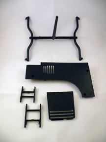
I opened the box and removed a runner with its sprue attached. I also found four parts in the box with the runner but no note. (I used to get notes, but the last couple of years I have been getting phone calls or e-mails instead.)
Business was slow on this particular day so I decided to go ahead and work up a review on the contents of the box.
|
The black parts were fairly flexible, probably made of polypropylene. The appearance was not very good: I saw sink all over the front side of the big part and what appeared to be glossy spots in the EDM finish. The sink was exactly opposite the ribs on the inside of the part.
Now, sink is mostly caused by a couple of things: Either the molder is not using enough pack and hold pressure or the ribs are thicker than they should be. Sure, it could have been a mold water problem, a gate that was too small, or a nozzle orifice on the small side. So I needed to look at the gate sizes, the nozzle orifice, and the rib thickness—pretty much in that order. Besides, I didn’t have a processing sheet to check the pressures and mold temperatures.
This was a four-cavity family mold with each part a different size and weight. Proper sizing is a little more difficult to do with subgates, and much easier with edge gates. However, I do not think the problem with these parts lay in the differences between sub- and edge gates. I say this because the biggest part was the one with sink on the cosmetic side. The second-largest part was fairly free of sink and both smaller parts had no sink at all. This looked to me like a gate size problem on the largest part only.
As I looked at the subgates, I saw another problem: They were feeding into an ejector pin that had a thin vertical section cut off on its end to allow for material flow. This was done to leave a flow path for the material to be injected into the pin and flow from the subgate up through this thin sliver section and into the part cavity.
The problem with cutting off part of the pin is that part cosmetics in the area where the plastic enters the cavity are always going to be visually unacceptable due to gas marks, blush, or sink on the part directly above the gate sliver.
I prefer to use a wedge-shaped ejector pin gate in every situation I have ever run across. The wedge shape allows the material to go from thick to thin as it flows through the ejector pin on the way to the cavity. The thick part of the wedge should be where the subgate is located and the thin part of the wedge should be where the plastic enters the cavity. For a typical part with a wall thickness of approximately 0.100 inch, I make the thick portion of the wedge 0.150 inch thick and the thin part 0.090 inch.
|
Another advantage of the wedge shape is that the subgate can be opened up to help fill and pack the bigger part, and since the ejector pin gate is usually clipped off and ground up or just left on the inside of the part, we don’t care if the subgate tears or peels.
The disadvantage of the wedge shape is that it cannot be used on small-diameter ejector pins as well as it can be with larger-diameter ejector pins. Ejector pins with diameters of 0.250 inch or larger make the best and longest-lasting ejector pin gates. Of course, oversized ejector pins can be used to replace those with small diameters if someone is concerned about breaking the wedge portion of the pin.
Bump up the sprue
Next, I checked out the runners, sprue, and the molding machine nozzle orifice size in relation to the sprue O-diameter.
The rib thickness where the sink was showing on the large part was 0.050 inch, which is perfect for parts with a wall thickness of 0.100 inch.
The subgate diameters were all 0.050 inch—a little surprising since the subgates were feeding into cavities where the volumes differed so much. This meant the subgate for the big part was too small, the subgates for the little parts were too big, and the sizing was just right for the middle-sized part (remind you of Goldilocks?).
After my visual inspection of the runner system, I found that the sprue and runner appeared to be sized large enough to be effective, but I always like to measure to be sure. I started with the part wall thickness—all seemed to be about 0.100 inch.
In general, the subrunner diameter that feeds the gate needs to be 1.5 times the wall thickness for a crystalline material like polypropylene, which means the subrunner diameter should be at least 0.150 inch. This subrunner was 0.175 inch, so we were OK. Remember, a little bigger generally works OK, but not smaller.
With subrunner diameters at 0.175 inch, the main runner needed to be 0.225 inch; at 0.250 inch, it was fine. A 0.250-inch main runner requires a 0.312-inch sprue O-diameter, but this one was just 0.220 inch. This meant the sprue O-diameter would have to be increased to 0.312 inch using a general-purpose nozzle with an orifice diameter of 0.290 inch.
I’m glad we caught this sprue O-diameter size problem before we finished our review. A small O-diameter causes pressure loss as we inject plastic through the too-small nozzle. It may not seem like such a big problem, but it causes the molding technicians to either raise their barrel heats a little bit or increase the injection pressure, and any increase in heats will require a slight slow down in cycle time. Finally, a narrowing of the processing window will often result from either of these conditions.
All that was left was to check the subgate diameters. For polypropylene, the gate diameters need to equal 50% of the wall thickness of the part. In this case, the wall thickness was 0.100 inch, so the gate diameter needed to be 0.050 inch. But these parts all varied in volume, so the big part gate would probably be more like 0.060 inch in diameter, the middle-sized part would be 0.050 inch, and the two little parts would probably be 0.040 inch.
These were just guesses at this point, but with a family mold, I always cut the big gate first, get the part to fill and pack and cycle like I want it to, and then cut the next biggest part gate. Then I repeat the process until all gates are cut. Whether it’s a two- or 20-cavity family mold, it’s always the same procedure.
My instructions to the molder were to install a sprue bushing with a 0.312-inch sprue O-diameter and increase the gate diameter of the big part about 0.010 inch. The latter may need to be opened up another 0.005 or 0.010 inch after the mold is sampled, but it is definitely better to be steel safe (at least this is what toolmakers always tell me).
When I heard back from the molder and his toolroom supervisor, they said the results from these changes were better than they imagined they would be. Their customer was also pleased that they were able to speed up the cycle enough to pass on a nice price decrease. Better-quality parts and a better price—that’s a win/win situation any way you look at it.
Troubleshooter’s notebook
Part/material: Polypropylene
Tool: Four-cavity family mold
Symptoms/problem: Glossy spots and numerous sink marks on the cosmetic side of the largest part, generally opposite the ribs.
Solution: Install sprue bushing with a larger O-diameter; increase subgate diameter of largest part and reduce same for smallest part; be sure nozzle is general-purpose type; most of all, switch to wedge-shaped ejector pins for better material flow.
About the Author(s)
You May Also Like


