Sign up for the PlasticsToday NewsFeed newsletter.
Sponsored By
The Troubleshooter, Part 24: Plating problems with platable ABS
August 3, 1998
9 Min Read
.svg?width=850&auto=webp&quality=95&format=jpg&disable=upscale "The Troubleshooter, Part 24: Plating problems with platable ABS")
This article continues our series of troubleshooting reports from one of the leading on-the-spot problem solvers in the molding industry. Bob Hatch is manager of technical service and customer support for Prime Alliance, the Des Moines-based resin distributor. Before his present assignment, Bob managed a molding operation for 25 years.
It was a quiet Friday afternoon and I was contemplating going home for the day when the FedEx truck showed up with a package. It was from some molders that I had visited once before, but at the time they were reluctant to make any of the changes I suggested. They thought they could work the problems out with heats, speeds, and pressures.
|
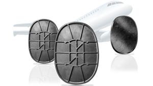
Figure 1. The variance in thick and thin sections in this part were the cause of the stress placed on this ABS part during molding, resulting in imperfect plating. |
Needless to say, you can't always work the problems out by raising the melt temperatures, slowing down the injection speed, and cooling off the mold to keep the parts from warping. This part of theirs is a perfect example of a problem that couldn't be processed out.
The real underlying issue here is not just molding good parts, but also the need to mold parts to be electroplated after molding. The molders were using a plating grade of ABS and they needed to get finished parts that would not show cracks and crazing after plating in the more highly stressed areas of the parts. Plus, it's not ideal when the plating peels off at the touch of someone's fingernail.
High Heats
After looking at the parts and the processing sheet, I could see they were molding the plating grade of ABS pretty much like they should, although perhaps the heats were a little on the high side. According to the setup sheet, the material heats were currently being run at 500F, both halves of the mold were at 185F, and the injection speed was slow, all of which resulted in a cycle about twice as long as it needed to be. Actually, both the material and the mold temperatures were too high, but that is apparently what they had to do to get good looking parts. The parts couldn't be plated but they did have a nice cosmetic look to them.
I could see the sprue, runner, and gates were not designed for plating-grade ABS--or any ABS for that matter--because the gates and runners were undersized, which is no doubt why the heats were on the high side. Therefore, the cycle time was longer than necessary due to the barrel and mold temperatures being too high. This is the same vicious circle I generally run into, except this time they were molding nice looking parts. It was just that they couldn't get them to plate like they wanted.
For the best looking plated parts I generally try to run the melt temperature of the material in the 450F range, the mold at 140F with the injection speed slow, and the injection pressure below 1000 psi.
Optimizing Steps
I decided to suggest that the molders start the work of optimizing the mold by working with the flow path to open it up to my plating grade ABS numbers. They currently had a .125-inch orifice in the heated sprue bushing that fed the runner, and the orifice should be at least a .312-inch orifice to feed a main runner of the size they were going to need. The main runner was .225 inch and it should be .275 inch at least. The subrunners were .175 inch and they should be .250 inch minimum for ABS for parts with walls this size and especially for parts that will end up being plated.
The length-of-flow requirements that I normally factor in were not as important in this case, mostly because the parts were small, so the requirement for material flow past the gate wasn't the same as with bigger parts. It's the nonuniform wall that appeared to be the problem from what I could see.
Stress and the Plating Problem
The part was about the size of an overcap on an aerosol spray can, but with wall thicknesses ranging from .165 inch on the bottom edge skirt and on a rib at the top of the part to the middle section of the part wall at .330-inch thick. Threads were on the inside diameter about half way between the top and bottom of the part.
The threaded section appeared to be acting like a shrink fixture for the rest of the part. The .330-inch-thick section of the part was shrinking long after the .165-inch threaded section of the part was frozen in place, which caused the stresses that were showing up on the side of the part during the acetic acid test.
|
Figure 2. Opening up dimensions in the melt delivery system reduced stresses on the part and resulted in a more platable end product. |
The ASTM acetic acid test, which is performed on parts during a quality control check, requires immersion of the parts in Glacial acetic acid liquid for 30 seconds, removal of the parts, and a rinse with plain water. Then the procedure is to do a visual check for whitish marks or crazing that will indicate areas of high stress. This procedure is the ASTM D-1939 specification for rigid ABS parts that are injection molded or extruded.
The parts the molders sent me had a white ring around the outside of the part where the thick and thin sections met, indicating stress was present in that area of the part. I could also see some of the sample parts that had been run through the second part of the acetic acid test, which is a 2-minute immersion of the parts in the liquid. Then the parts are washed off as before, and the visual inspection performed.
In this more severe test I could actually see small cracks and some crazing on the part in the same area where the whitish ring was in the 30-second test.
Redesign Preferred
The only long term answer I could see was for the customer to redesign the part and make the wall thicknesses more uniform. I like to see the wall thicknesses be at least within 10 percent of each other for a well-designed part. When I called the molders they said that redesign was out of the question, at least right then. Maybe later, but not then.
This problem is a common one that I run into with customers that have the newer closed loop process control on their molding machines. The molding technicians have been able to fill and pack all the cavities in this mold by starting slow (about 30 percent) with the injection speed to get the plastic through the runner and gate (which avoids a blush or jetting at the gate), then speeding up (90 percent) to fill the majority of the part, then slowing down again at the end of fill to give any trapped air time to get out of the mold.
Then they pack out the voids in the side wall by raising the hold pressure to about the same as the injection pressure, actually just a little bit higher. This profiling allows them to mold parts with less than ideal sizing of the nozzle orifice, sprue, runners, and gates, but it does work and I did not see any voids in the thick sections of the parts that I split in two to look at the cross-sectional area of the part.
Remember to split the parts to look for voids (I just crunched them in a bench vise). Don't cut them on a bandsaw, because quite often the bandsaw blade heats the plastic up and the hot plastic seals the surface. As a result, you can't see the voids in the parts.
The answer for this problem is to open the flow path, primarily the gate size and the orifice of the heated sprue bushing. In this way, the heats can be reduced to lower levels and keep the gates open while the holding pressure is pushing extra packing material into the airless voids as they form in the thick sections of the parts. A possible Bandaid solution would be to try slowing down the injection speed through the middle section of the parts to see if the crazing is being caused by the fast injection speed currently used in that section of the parts.
I passed all of my suggestions on to the molders and they tried the slower injection speeds and it did help some, but the gate kept freezing off as evidenced by packing rings around the gate area. The next step was to open up the heated sprue bushing orifice and double the size of the gate.
This was enough to allow the material melt temperature to be lowered to 450F and the mold temperature to be brought down to 140F. The parts looked pretty good to the molders, and the parts didn't show any stress when subjected to the acetic acid test. This is one of those cases where they didn't have to do all the things I usually feel are necessary to mold great parts, but only because they could use the speed profiling on the machine to make up for deficiencies in the runner system.
This problem was unusual only due to the plating requirement of the molded parts. If they hadn't needed to plate the parts they would have been OK with just injection speed changes, but this time more was needed to produce acceptable parts. You never know how much optimizing it is going to take to get the job done. This time we were lucky and we were able to mold parts that plated well with only two changes to the mold.
TROUBLESHOOTER'S NOTEBOOK
Part: Overcap.
Material: Platable ABS.
Tool: Four-cavity, cold runner mold.
Symptom: Imperfect plating.
Problem: ABS subjected to too much stress because of uneven wall thickness, thus uneven cooling, and improperly sized gates and runners.
Solution: Enlarged heated sprue bushing orifice, runners, and gates; recommended part redesign for more uniform cooling.
Result: Plating was acceptable.
You May Also Like