The Troubleshooter, Part 58: Sizing runners
This month, the Troubleshooter starts a series on his Rules of Thumb with proper calculations for runner sizing. The series continues in the April issue with gate sizing. Bob Hatch is manager of technical service and customer support for Prime Alliance, the Des Moines-based resin distributor. Before his present assignment, Bob managed a molding operation for 25 years.
February 1, 2003
This month, the Troubleshooter starts a series on his Rules of Thumb with proper calculations for runner sizing. The series continues in the April issue with gate sizing. Bob Hatch is manager of technical service and customer support for Prime Alliance, the Des Moines-based resin distributor. Before his present assignment, Bob managed a molding operation for 25 years.
 For the initial portion of the design process, I start my designs with the runner or subrunners that feed the gate(s). First, I need to know the type of material being used and the flow length of the material from where it loses its heat source. In all cases, this location is either the nozzle of the molding machine, a hot tip gate if using a hot runner system, or the orifice in a heated sprue bushing.
Amorphous materials such as polystyrene, SAN, acrylic, ABS, or polycarbonate need bigger runners—based on the wall thickness of the part—than crystalline resins. Crystalline resins include polyethylene, polypropylene, acetal, nylon, and PBT polyester.
I also need to know the wall thickness of the part we are going to mold before I can get started. For this exercise we will use a nominal wall of .100 inch and ABS as the material.
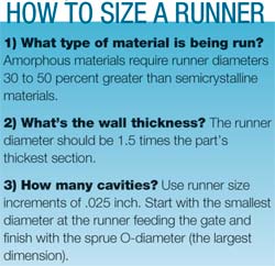
Next, I need to know how many cavities are involved. For this exercise we will calculate the runner sizing for a 16-cavity mold. Each runner level up from the runner that feeds the gate needs to be larger in diameter by .025 to .050 inch. I most often use .025 inch as my incremental number but have used .040 inch when working with metric-based customers. With metric sizing calculations I can make the runner level jumps in multiples of .040 inch and end up with runner sizing of 3, 4, or 5 mm in my final calculations. This metric approach just seems easier to me and I suspect I am drifting towards using millimeter or .040-inch jumps in all of my runner calculations.
 A few years ago I attended a seminar where the instructor suggested runner level jumps of .050 inch each. While I find these jumps of .050 inch to work quite well, I prefer to use .025 inch jumps between levels. This increment allows me to size a runner that meets my needs without exceeding an acceptable regrind level (usually less than 25 percent).
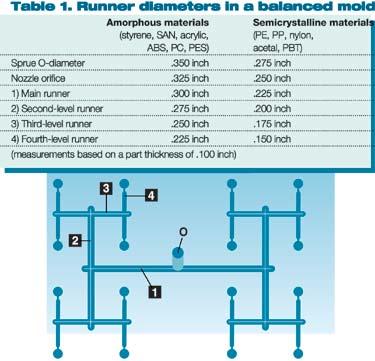
For the .100-inch wall thickness, referring to Table 1 indicates that for ABS material I need a diameter of .225 inch for the subrunner that feeds the gate (fourth-level runner). The basic rule for this calculation is that the runner diameter must be 1.5 times the thickest section of the part. I have found that if this rule is not followed, sinks and voids don’t pack out.
Notice that amorphous materials require a larger diameter than the rule calls for. Amorphous materials are more shear sensitive than crystalline materials, so I bump up my sizes 30 to 50 percent when calculating runners for amorphous materials.
Now that I have the calculation for the subrunner that feeds the gate, I apply the appropriate diameter from the chart for each of the runner levels heading towards the sprue. The next runner level, number three, is .025 inch larger than runner four, or .250 inch in diameter. Next up is runner two, which is .275 inch, and the main runner is .300 inch. With the runners sized, we now move on to the sprue bushing and nozzle orifice. As we move from the main runner to the sprue O-diameter (small end of the sprue), we double our jump number so we can fit the nozzle orifice size between that of the sprue O-diameter and the main runner diameter. This means we jump .050 inch from the main runner size of .300 inch to a sprue O-diameter of .350 inch. Then we size the nozzle orifice .025 inch smaller than the sprue O-diameter, making the nozzle orifice .325 inch.
|
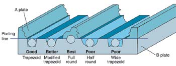
Figure 1. Full-round runners are the best design for any gate, but half-round or trapezoidal runners can be used with subgates. |
Nozzle, Runner Shapes
With sizing completed, it’s time to consider the type of nozzle that will work best with the material being run. Amorphous materials such as ABS require a full taper nozzle on the molding machine as they do not like or need shear points. Nozzles other than a full taper design cause shear points in the material’s flow path.
Shear splay, dark streaks, and other cosmetic defects often seen on molded parts can be traced back to using the wrong style of nozzle. It is also why molding technicians are forced to use higher barrel melt temperatures in their process setups, and we all know that higher barrel melt temperatures can cause longer cycles.
Next, we need to be sure that the runner design is appropriate for the type of gate being used. Figure 1 shows the relationships of flow channels when using different runner designs.
A full-round runner of the correct diameter is always a good design choice for any type of gate but an absolute requirement for an edge gate. The edge gate also needs to come off the center of the full-round runner and pass through an abrupt transition as it goes through the gate. An edge gate that comes off the side of a full-round runner is considered a high-shear gate and can cause blush on the surface of the part just inside the gate.
While full-round runners work well for edge gates, they also work for subgates and three-plate runners where the runners transition into individual drops.
Half-round or trapezoidal runners should only be used with subgates. You can also use a trapezoidal runner design for feeding the drops in a three-plate runner design. Be careful when designing trapezoidal runners since the depth, not the width, of the runner should be used for the flow calculation.
About the Author(s)
You May Also Like


