What are the hidden risks
of tool transfers? Part 1
There are serious strategies for moving tools worldwide, but the decision process should start at part design, not when the mold hits the back dock. In this four-part series, a transferred tool is set up in three different machines; only one produces a good process window. First up: Machine #1.
October 15, 2009
There are serious strategies for moving tools worldwide, but the decision process should start at part design, not when the mold hits the back dock. In this four-part series, a transferred tool is set up in three different machines; only one produces a good process window. First up: Machine #1.
I have been in this industry almost 30 years, but lately I’ve been hearing about an incredible number of tool transfers happening. Highly influential people in our industry predicted 20,000-100,000 tools would be transferred between molding facilities in the near future. More recently, I have heard those numbers may be greatly underestimated.
I visit facilities nearly every week and get to have conversations with a lot of key people. One project engineer told me that he was responsible for more than 1400 tool transfers by the end of this year. These numbers are staggering, even though tool transfer is nothing new to our industry; companies have always moved tools around due to cost reduction opportunities, market trends, financial problems, and so on.
I remember all the tool transfers going into Asia from other countries a few years ago, although it did not receive the same publicity that we are seeing today. I don’t wish to downplay the significance of what is going on; it’s enormous. However, the one commonality over the years has been the lack of a solid data-driven approach to moving tools, or a data-based strategy for success in that endeavor.
|
When I hear questions such as, “The mold fits between the tiebars and you have more than enough shot size, so what’s the problem?” or “They got good parts out of this tool at the other place—why can’t you?” I get very nervous because they betray a lack of understanding about what processing truly is—that there is actually a recipe for choosing the appropriate molding machine performance to support the requirements of the mold.
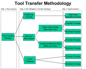
First, let’s look at the decision-making process of a tool transfer, the information needed to make good judgments, the risk level (understanding that not every tool is a good candidate for a transfer), and why some processes cannot be duplicated—they must be rebuilt (Figure 1).
Risky business
Every tool transfer has a certain amount of risk. Let’s break this down into steps, starting with risk analysis. Later in this series we will break down the risk factor into a numerical value. The first and most important idea to understand is that a tool transfer requires information from many sources.
Barrel capacity. The first piece of information to gather is whether or not the mold is running in a machine where barrel capacity used is between 20% and 80%. Why is this so important? Because if you use less than 20% of the barrel, getting the screw up to the appropriate injection speed will be a challenge, to say the least, and it could be impossible. For instance, if I placed two orange flags 100 ft apart and asked you to pull your car up to the first flag, then gave you instructions to go 100 mph and stop at the second flag, you would probably not reach the speed requested, and stopping may be an issue.
Screw rotation. Another item to consider is how many times the screw rotates to achieve a shot size that small or to generate a good homogeneous mix of material. If more than 80% of the barrel is used, residence time could be a problem. With a tool transfer this is critical. If the machine that was running this job was using 40% of the barrel with an injection speed of 5 in/sec, and the machine you are going to select uses 15% of the barrel capacity and you input 5 in/sec on the control, you may not reach that speed due to travel distance. Also, you will not achieve the same viscosity, shear rates, orientation of the molecular chains, and pressure loss across the cavity, so you will miss the shrink rates that the other processor achieved and therefore the dimensions. As you can see, this chain of events can cause a disaster and puts you in a high-risk scenario on this tool transfer.
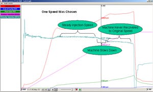
When this machine gets near the maximum injection pressure, it starts slowing down (Figure 2). During the early portion of fill, the injection speed remains fairly consistent; when it reaches the later portion (near the cursor), the machine inherently slows down. This machine may not deliver the material in the same manner as the machine in which the process was built.
Remember, too, that the process should not have been pressure limited or be pressure limited in the transfer machine, as this also affects the material’s delivery inside the cavity. If the process is pressure limited, you will not be able to handle a viscosity shift. For example, if my peak pressure at transfer is 15,250 psi and you are using a machine with an intensification ratio of 10:1 and your pump pressure is 1800 psi, the maximum plastic pressure you can generate is 18,000 psi. If the viscosity never shifts, you might be OK. However, if the viscosity goes up by 20%, your new peak at transfer may rise to 18,300 psi, which means you are pressure limited by default, and you need more than the machine makes, causing you to take higher risk with the tool transfer.
Viscosity. Plastic material manufacturers develop materials that exhibit a viscosity shift ±10%, which is a 20% swing. This also depends on what type of materials you buy. For example, if you are purchasing a wide-spec material, this viscosity shift could be larger, but the material less expensive. Processors have a responsibility to manage this viscosity shift appropriately. If I set the backpressure or rpm settings incorrectly, I could incur a wider viscosity shift.
With tool transfers, I would ask the following questions: Are you managing the viscosity the same way the previous processor did? Do you know if the screw is the same or different? For example, if the other molder was running polypropylene with a semicrystalline screw and you use a general-purpose screw, the material may have a different viscosity and your parts will differ. We don’t always have all the information about how a process was previously producing parts, but we do know that this process can’t be matched; it must be rebuilt.
Machine size. The mold must cover no less than two-thirds of the platen between the tiebars. If the machine the mold came from was a 500-tonner and it covered two-thirds of the platen, and the machine it’s moving to is a 750-tonner and it covers only half of the platen, clamp force and platen deflection could be very difficult to repeat; and depending on if the machine uses toggle or hydraulic clamp movement, it could challenge the way the mold is supported.
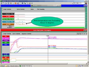
Note that the amount of heat loss between these two platens will be much different, potentially changing the performance requirements of the mold temperature control system to achieve the correct part cooling. When most tools are transferred, we have no idea how the mold was plumbed, what delta temperature was being achieved, or even how many gallons per minute were flowing through the waterlines. To repeat the process of heat removal is, at best, a guess. As you can see in Figure 3, what was going on with temperature inside the cavity was not repeating well, nor was it stable.
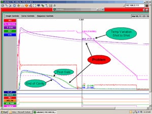
In Figure 4, the thermolator is struggling with this process and is not able to sustain a steady temperature inside the cavity. Any information missing about heat removal raises the risk to a higher level.
Machine performance. There’s a problem with the way some molding machines gather information on fill time. Let’s say, for example, that the process that was running in Machine A had injection speed set at 3.5 in/sec with correct tuning, and Machine B is also set at 3.5 in/sec but the tuning is significantly incorrect. It might actually achieve 2.5 in/sec. Many processors would just watch the fill time and try to duplicate it. But Machine A will start recovery (screw rotation) until the shot size is reached, and then decompress is achieved and the fill timer is reset; while Machine B will start recovery until the shot size is reached, and then the fill timer resets at that point and decompress is accomplished. So the same fill time on each machine is very different.
There are several more tests that should be performed on the machine, including pressure response, load sensitivity, check ring study, and repeatability. If your press performs differently, you may have to build a process to accomplish the same part quality, the difference between a process match and process rebuild.
In the next article we will start our tool transfer by first understanding the risk of poor part design and then two basic thoughts about bad part design: 1) transferring it will not fix it and 2) it raises the risk of a tool transfer.
Author Gary Chastain ([email protected]) is a consulting and training manager with RJG Inc. (Traverse City, MI).
Coordinating an acceptable transfer
With many molds currently on the move, and more to come as the industry realigns, e-mails such as the one on the right to tooling engineers will not be uncommon.
In this example, there are 30 tools from a project to send out. A molder understandably doesn’t want to spend a lot of time and resources on an outbound transfer, and the OEM is not likely to pay them to handle it. But apart from that, what are the basic required actions that must be taken to ensure the situation is handled correctly and professionally, so that a bridge has not been burned?
“When an entire product line is being moved, this is no small task,” says Steve Johnson, operations manager at ToolingDocs (Ashland, OH), which in addition to providing mold maintenance training and software, also offers a tool transfer service. “There are many considerations and closets to be cleaned out. Often, these product lines have been in operation for several years. A plan needs to be formulated for how this will all end up on the dock, ready to ship, on the required date.”
With the tooling engineer coordinating the transfer, a tool status spreadsheet is begun, and different actions will be needed from various departments, including:
Toolroom manager: Responsible for most of the preparation. List includes prepping molds for shipping and retrieving mold book, spare parts, and any special assembly/disassembly tooling unique to the tools.
Molding manager: Responsible for gathering the most recent setup sheets and any other known history of the tooling. Even though many companies view some of the information as proprietary, in this scenario we are trying to do the best possible job by forwarding at least the minimum basic information.
QC manager: Responsible for locating the most current piece part drawings as well as any special jigs or fixtures, last shots, and QC reports from each tool.
While it will be the decision of the plant manager and possibly other senior managers as to exactly what is provided, the tooling engineer’s goal is to pull in all the elements for a punctual transfer, free of gaps to chase down later, and free from damage that will result in potential fingerpointing and liability.
When all is on the dock, the tool status spreadsheet can be forwarded to the plant manager, and should any questions or conflicts later emerge, evidence of a responsible transfer is now on file. A potential dispute can be avoided, and an opportunity to maintain and grow the OEM relationship might still be achieved.
Coming next: Specifics for the toolroom manager charged with preparing the molds for transfer.
Author Randy Winton ([email protected]) is global training manager at ToolingDocs.
Don't miss Part 2: Assessing risk in part design.
About the Author(s)
You May Also Like
