WEB EXCLUSIVE: Want to get more out of your press? Check the oil
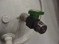
Installation of a sample valve with end cap located at the midsection of the hydraulic system reservoir provides a simple and consistent way of obtaining oil samples.
March 1, 2008
|
Like your car, an injection molding machine requires regular maintenance, including checking and changing the oil. Work that into your PM program and watch the costs go down and the output go up.
Hydraulic systems are an integral component to injection molding machines, delivering the power needed to mold plastic into a spectrum of products. With the industry moving toward increased clamping and discharge pressures, smaller reservoirs, and extended operating schedules, these fluid power sources are under more pressure than ever to perform so elevated production goals can be met.
To this end, maintenance professionals are challenged with implementing maintenance programs that can optimize the durability and performance of their hydraulic systems, which are increasingly subjected to extreme operating conditions.
A key element to any successful proactive maintenance plan is oil analysis, monitoring the condition of lubricating fluid so issues can be identified and addressed before they begin to impact production.
A comprehensive ongoing oil analysis program can enhance hydraulic system performance, minimize maintenance costs, and boost productivity. By maintaining viscosity, examining element content, keeping oil clean, minimizing oxidation and nitration, identifying water content, and monitoring copper leaching, maintenance pros can streamline production.
Step 1: Taking samples
It's important to take samples when the hydraulic system is in use. There are several areas on a hydraulic system where samples can be taken: from the reservoir or sump with a vacuum pump, or from a sample valve located on a pressurized return line, valve block, or reservoir wall. Installing a sample valve with end cap at the midsection of the hydraulic system reservoir provides a simple and consistent way of obtaining oil samples.
To identify the most appropriate sample point, consult with your oil analysis provider and machine manufacturer. Once the spot is identified, it should be noted in the maintenance records so samples can always be taken from the same place. This will ensure that all test results provide the most accurate reporting.
Industry standards recommend sampling used oil every quarter. However, it's highly recommend that sampling be conducted more frequently if:
there are abnormal levels of wear or contaminant elements.
vibration readings are increasing.
there's an increase in temperature throughout the fluid system.
there's been an overhaul or pump change-out.
new pieces of equipment are put into service.
Storing results and identifying trends enable maintenance professionals to react to hydraulic issues early, avoiding major concerns down the line.
Maintaining proper viscosity
Viscosity is the measurement of a lubricant's resistance to flow. A fluid with the correct viscosity characteristics will provide the appropriate level of critical hydraulic component protection and promote optimized hydraulic system efficiency.
Recommended viscosity grades for hydraulic fluids are typically ISO 32, 46, or 68. Lubricant viscosity can fluctuate due to several factors, but contamination and shearing of high-viscosity-index improved fluids are the most prevalent for hydraulic systems.
A fluid can become contaminated by someone topping off the reservoir with a different fluid, by improper storage and/or handling methods, or by any airborne contaminant ingression into the in-service fluid.
If viscosity decreases, premature equipment wear and increased fluid consumption through leakage could result. Increased viscosity can lead to pump cavitation and reduced hydraulic efficiency.
Typically, viscosity fluctuation indicates that the performance of the lubricant is being compromised and may not be able to provide sufficient equipment protection. In general, if a fluid's viscosity at 40°C changes more than 15% above or below its original viscosity grade, it should be closely monitored. Work with your oil analysis provider to resample and investigate before changing lubricant. It can save you money on fluid expenditures.
Examining element content
Three element types can be found in oil: wear, contaminant, and additive.
Wear metals are the metals removed from equipment components such as bearings, gears, and pumps by wear, friction, or corrosion. Oil analysis techniques measure these wear elements, and since most machinery components have a metallic signature or “fingerprint,” it's often possible to make informed conclusions about the condition of machinery components from the oil analysis data. For hydraulic systems, iron from pump bearings and copper from pump and heat exchanger components are the wear metals commonly found during oil analysis. Each wear metal affects fluids differently, so your oil analysis supplier can help you make good decisions regarding fluid condition.
Common contamination elements for hydraulic fluids include silicon and sodium that can enter the oil through airborne dirt, water cooler leaks, and improper storage or handling. Increases in abrasive contaminants such as silicon can increase wear rates. Increased sodium typically indicates low-level water contamination that may not be caught in typical water content analysis. Trending of contaminant elements can head off failures from faulty system components or improper storage and handling.
Additive elements can also be monitored by oil analysis to gain insight into the remaining life of in-service oil. Typical hydraulic fluid additives include phosphorus and zinc (to enhance antiwear protection and prevent oil oxidation) and calcium (for rust protection). Additives can become depleted during normal operation, and some may be removed through water contamination. A key indicator of a good hydraulic fluid is its ability to retain antiwear additive elements over the long haul. Monitoring additive elements relative to new oil levels is also important.
Operational longevity depends on many factors; however, three to five years is an acceptable lifespan of a hydraulic fluid, and higher-performing fluids have service lives upwards of seven years.
Keeping your oil clean
Oil cleanliness can be defined by the level of dirt or other insoluble or hard particles in fresh or in-service oil. Among the most notable causes are contamination and harsh operating conditions such as extremely high temperatures, pressures, and operating speeds.
Particle counting is an industry-accepted approach to determining a cleanliness rating, accounting for particles >4 µm, >6 µm and >14 µm. For perspective, the width of a human hair is about 40 µm.
Cleanliness is a comparative value that should be analyzed in conjunction with values of previous samples and an unused sample. However, hydraulic fluids should maintain a cleanliness level consistent with the components that have the smallest dynamic clearance, typically the control valves.
To support this level of cleanliness, maintenance professionals should consider installing filters before and after the pump, as well as separate servo valve and/or return line filtration. The strainer protects the pump, the pressure filter protects the actuator, the servo filter ensures proper servo operation, and the return line filter helps the reservoir stay clean.
|
Minimizing oxidation and nitration
Oxidation and nitration produce tenacious deposits, causing hydraulic systems to operate erratically, and shortening both system component and oil life.
Though typically mentioned together, oxidation and nitration are actually very different. Oxidation is the reaction of oxygen with the hydrocarbon molecules in the hydraulic fluid. The oxidation rate increases exponentially as temperature rises and with metallic contaminants. Increases of 18 deg F (10 deg C) in the oil temperature will effectively double the oxidation rate. Copper, bronze, brass, and iron contaminants are typical materials that can catalyze oil oxidation reactions.
Nitration indicates a fluid is reacting with nitrogen oxide compounds, and creates varnish that sticks primarily to valves. Field tests show that nitration increases when ambient air temperatures rise and/or loads become higher. Additionally, mechanical conditions such as a lower oil makeup, poor ring sealing, and poor ventilation also expedite nitration.
Both conditions can be monitored through infrared (IR) testing to measure the levels of oxidation and nitration compounds in the oil relative to a new oil sample. Typical analysis assigns a numerical oxidation or nitration rating measured in Abs/cm. Increasing ratings indicate that the fluid may be reaching the end of its useful life or that there is an operational problem with the system.
As previously noted, oxidation and nitration often leads to insoluble materials in the fluid that result in system deposits that effect system operation. Ultra centrifuge testing measures insolubles content, and also submicron particles (typically less than 0.5 µm) that are precursors to deposits. While this test is not commonly part of routine oil analysis, it is recommended for hydraulic systems that operate at 65°C or above and systems that use fine-tolerance servo and proportional valves. Ultra centrifuge ratings are reported on a scale of 1-8. UC ratings above 4 should cause concern that system deposits will be generated.
Identifying water content
Remember: Water and lubricants just don't mix, so water content of hydraulic fluid should be monitored.
Water can contact hydraulic fluid via cooler leaks, condensation, or from wash-down. As water content rises, the lubricant's oxidative stability and performance deteriorates. Loss of viscosity and/or hydrolysis from water in the lubricant may cause excessive friction of moving or rotating components. And excess water combined with heat can accelerate the formation of organic acids that lead to corrosion and ultimately to component failure.
Hydraulic fluids start to look milky as water content increases. When water reaches 500 ppm, the fluid should be closely monitored. At 1000 ppm, the fluid should be changed.
Monitoring for elevated copper levels
Pumps often use copper alloys, as do shell and tube heat exchangers, and given the right conditions, copper may leach into the oil from these components. Depending on the lubricant, the copper may interact with other additives to form soluble chemical complexes that can be observed in routine analysis, or the leached copper simply may be “dropped” from the oil and hence be invisible to routine oil analysis methods.
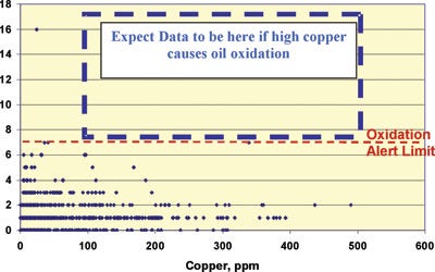
Elevated copper levels (typically less than 500 ppm) may be seen in as little as 50-250 hours of run time. Research indicates the copper content levels off with continued operation and does not affect performance characteristics or oxidation stability of the fluid. More than 900 used oil analyses of a premium hydraulic fluid done between 1993 and 2006 in plastics injection molding systems with copper tube heat exchangers found no correlation between elevated copper levels and increased oxidation for oils of this formulation (see chart).
Following these recommendations, maintenance professionals can benefit from optimized hydraulic performance, streamlined production, and minimized maintenance.
Author Andy Lyczak is a lubrication engineer at ExxonMobil Lubricants & Specialties (www.mobilindustrial.com).
About the Author(s)
You May Also Like


